Thyristor controlled short circuit current limiter

A technology of thyristor control and short-circuit current, which is applied to emergency protection circuit devices, electrical components, circuit devices, etc. for limiting overcurrent/overvoltage, and can solve problems such as not being simple enough, cost-effective, and expensive, and achieve structural Simple, easy-to-use effects

Inactive Publication Date: 2013-10-23
SHANDONG UNIV
View PDF3 Cites 0 Cited by
  • Summary
  • Abstract
  • Description
  • Claims
  • Application Information

AI Technical Summary

Problems solved by technology

[0004] Invention patent No.: 2003101235398 "Superconducting Saturated Core Fault Current Limiter" proposes a current limiter that uses the saturation characteristics of the core of a magnetically saturated reactor to form a current limiter. This kind of fault current limiter requires superconducting materials and is expensive. The performance of superconducting materials is unstable, and the maintenance equipment is complicated
Invention patent No.: 2004100802846 "a fault current limiter" also proposes a current limiter that uses the saturation characteristics of the iron core of a magnetically saturated reactor to form a current limiter. The disadvantage of this current limiter is: to provide DC current to the DC coil The circuit is complex; the effect of limiting short-circuit current is limited; only the effect of limiting short-circuit current is not high cost performance, etc.
However, these devices are not economical enough and simple enough

Method used


Image

  • Thyristor controlled short circuit current limiter

Examples


Embodiment Construction

[0019] The present invention will be further described below in conjunction with the accompanying drawings and embodiments.

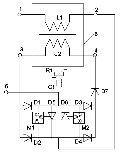
[0020] A thyristor controlled short circuit current limiter such as figure 1 shown. The saturable reactor has four terminals; the reactance coil terminal I1 and the reactance coil terminal II2 are connected to the internal reactance coil L1 of the saturable reactor to provide an AC current path; the DC coil terminal I3 and the DC coil terminal II4 are connected to the internal DC coil L2 of the saturable reactor to provide DC current path; reactance coil L1 and DC coil L2 interact through the closed-loop iron core inside the saturable reactor; figure 1 The structure and connection of a controllable saturable reactor shown in the saturable reactor 6 is a schematic diagram.

[0021] The reactance coil L1 in the saturable reactor 6 may be composed of a plurality of coils in series and connected in parallel, and the DC coil L2 in the saturable reactor 6 m...


PUM


Abstract

The invention relates to a thyristor controlled short circuit current limiter. In the limiter, a reactive coil L1 and a direct current coil L2 form a saturation reactor; the reactive coil L1 is used as an alternating current passage; the direct current coil L2 is used as a direct current passage; the reactive coil L1 interacts with the direct current coil L2 through a closed loop iron core in the saturation reactor; one end of the reactive coil L1 is connected with an input end of a full bridge rectifier circuit, and the other end of the reactive coil L1 and the other input end of the full bridge rectifier circuit are connected with an external circuit; an output end of the rectifier circuit is connected in series with a forward diode D7 and the direct current coil L2 to form a closed loop; two thyristors D5 and D6 are reversely connected in parallel between two input ends of the full bridge rectifier circuit; the thyristors which are reversely connected in parallel are controlled by control modules of the thyristors respectively; each control module is provided with three terminals; and two of the three terminals are connected with the positive electrode and the negative electrode of the controlled thyristor D5 or D6, and the third terminal is connected with a touch end of the controlled thyristor D5 or D6.

Description

technical field [0001] The invention relates to the technical field of power transmission and transformation in power systems, in particular to a thyristor-controlled short-circuit current limiter. Background technique [0002] With the continuous development of the power system and the continuous increase of power generation capacity, the short circuit current caused by the short circuit of the power system is very large. The short circuit current caused by the short circuit in the power system is very harmful to the power system. Therefore, reducing the short-circuit current can reduce the damage degree of the power equipment during short-circuit and improve the stability of the power system. [0003] In recent years, research on methods and devices for limiting short-circuit current (also called short-circuit current limiter) has become a hot topic. [0004] Invention patent No.: 2003101235398 "Superconducting Saturated Core Fault Current Limiter" proposes a current lim...

Claims


Application Information

Patent Timeline
Patent Type & Authority Patents(China)
IPC IPC(8): H02H9/02
Inventor 李晓明
Owner SHANDONG UNIV
Why Eureka
Try Eureka