
Novel storage bin

A silo, a new type of technology, applied in the fields of chemical machinery and equipment technology, can solve problems such as difficulty in ensuring product quality, affecting fertilizer efficiency, and unstable product quality, avoiding secondary stratification, stable product quality, and low equipment cost. Effect

Active Publication Date: 2011-10-12
SHANDONG AGRI UNIV FERTILIZER TECH CO LTD
View PDF2 Cites 4 Cited by
  • Summary
  • Abstract
  • Description
  • Claims
  • Application Information

AI Technical Summary

Problems solved by technology

The production of blended fertilizers is relatively primitive, and some of them are mixed manually with tools such as shovels. This method is difficult to guarantee the quality of the product
Regular manufacturers have a relatively high degree of mechanization. Although the electronic batching system is used to solve the problems of continuous production and accurate batching, most fertilizers are subjected to various types of particles with different densities and particle sizes during the transportation process from production to packaging. The resistance is different, the running line speed is different, and different angles of repose are produced before static packaging, resulting in the classification and layering of the secondary material flow before packaging, which eventually leads to unstable product quality and seriously affects fertilizer efficiency.

Method used


Image

  • Novel storage bin
  • Novel storage bin
  • Novel storage bin

Examples


Embodiment 1

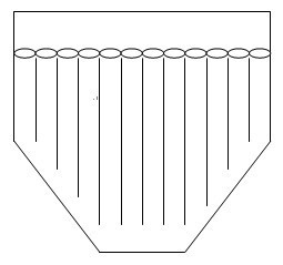
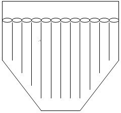
[0024] Such as figure 1 As shown, the unloading channel includes a plurality of unloading channels arranged in parallel, and the lower end of the unloading channel located directly above the closing slope of the lower bin body 2 in the unloading channel does not contact with the position of the corresponding closing slope. distance.

[0025] The above-mentioned distance should not be too large, otherwise the effect of avoiding delamination is not obvious, and it should not be too small, otherwise the material will not fall smoothly. The size of the distance can be selected to be the same as the pipe diameter of the feeding channel.

[0026] The above-mentioned distance between each feeding channel and its corresponding closing slope can be the same or different. When the same, the tapered surface formed at the lower end of the feeding channel directly above the closing slope is parallel to the closing slope.

[0027] The distance between the feeding channel directly above the...

specific Embodiment approach 2

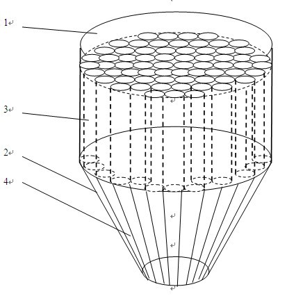
[0028] Such as figure 2 As shown, the feeding channel is provided with a feeding channel from the upper end surface of the silo to the bottom surface of the silo.

[0029] The upper unloading channel 3 located in the upper bin body 1 is a vertical channel arranged in parallel with each other, and the lower unloading channel 4 located in the lower bin body 2 starts from the junction of the lower bin body 2 and the upper bin body 1. The shrinkage shape, the shrinkage ratio is the same as the shrinkage ratio of the lower silo.

[0030] The present invention can be entirely made of metal or other anti-corrosion materials, and the silo can be widely used in dry powder, dry granule blending and stirring and cutting industries with different physical properties.

[0031] The cross-sectional shape of the feeding channel can be honeycomb, which has the advantages of compact structure and easy processing. At the same time, the angle formed between the cone busbar of the silo and the h...


PUM


Abstract

The invention relates to a storage bin. The novel storage bin comprises a bin body and is characterized in that: a material unloading passage is formed in the storage bin; and the material unloading passage is extended from an upper port of the storage bin to the lower part of the storage bin. When various particle materials with different specific gravities and shapes are mixed according to different proportions, the phenomenon that the running line speed of particles is different due to different resistances of particles with different densities and particle sizes in the throwing process, so the grading and secondary layering of products are caused by drop point difference of the particles in the conventional process is avoided, and the quality of the product and the stability of fertilizer efficiency are guaranteed.

Description

technical field [0001] The invention relates to the field of chemical machinery and equipment technology, in particular to a novel feed bin for avoiding mixing and delamination. Background technique [0002] At present, blended fertilizers with simple production process and flexible ratio are welcomed by farmers. The production of blended fertilizers is relatively primitive, and some of them are mixed manually with tools such as shovels. This method is difficult to guarantee the quality of the products. Regular manufacturers have a relatively high degree of mechanization. Although the electronic batching system is used to solve the problem of continuous production and accurate batching, most fertilizers are subjected to various kinds of particles with different densities and particle sizes during the transportation process from production to packaging. Different resistances lead to different running linear speeds, resulting in different angles of repose before static packag...

Claims


Application Information

Patent Timeline
Patent Type & Authority Applications(China)
IPC IPC(8): B65D88/28
Inventor 丁方军马学文陈士更朱军孟庆羽
Owner SHANDONG AGRI UNIV FERTILIZER TECH CO LTD
Learn More