
User terminals, wireless communication method and wireless communication system

A technology for a wireless communication system and a user terminal, applied in the fields of wireless communication methods, base stations and user terminals, can solve problems such as different relative relationships, different channel estimation accuracy, and channel estimation accuracy deterioration.

Active Publication Date: 2011-10-05
FUJITSU LTD
View PDF0 Cites 14 Cited by
  • Summary
  • Abstract
  • Description
  • Claims
  • Application Information

AI Technical Summary

Problems solved by technology

[0030] However, in the CAZAC sequence ZC with L=11 k (n) When circularly shifted and used by users 1 and 2, by Figure 28 It can be seen that in user 1 and user 2, the relative relationship between the pilot transmission frequency band and the data transmission frequency band is different, resulting in different channel estimation accuracy
That is, the subcarriers 23 and 24 in the transmission frequency band of user 2's data deviate from the transmission frequency band of the pilot, so that the channel estimation accuracy in the subcarriers deteriorates
[0031] In addition, in Figure 28 Among them, according to the current 3GPP LTE specification, the subcarrier spacing of the pilot is set to twice the subcarrier spacing of the data, but the above-mentioned problem also occurs when the ratio of the subcarrier spacing changes

Method used


Image

  • User terminals, wireless communication method and wireless communication system
  • User terminals, wireless communication method and wireless communication system
  • User terminals, wireless communication method and wireless communication system

Examples


Embodiment Construction

[0080] (A) Principle of the present invention

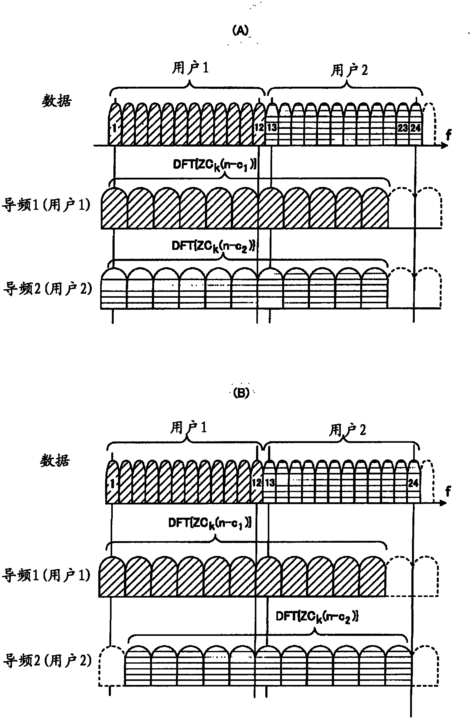
[0081] like figure 1 As shown in (A), in the pair CAZAC sequence ZC k (n) The result after implementing cyclic shift c1 is used as the pilot frequency of user 1, and the CAZAC sequence ZC k (n) When the result of implementing cyclic shift c2 is used as the pilot frequency of user 2, as in Figure 28 As explained in , in the data transmission frequency band of user 2, the subcarriers 23 and 24 deviate from the pilot transmission frequency band, deteriorating the channel estimation accuracy of the subcarriers. In addition, in figure 1 In, DFT{ZC k (n-c1)}, DFT{ZC k (n-c2)} are CAZAC sequences ZC for L=11 respectively k (n) implement cyclic shift c1, c2, and then ZC k (n-c1), ZC k (n-c2) Pilots in the frequency domain obtained by performing DFT processing.

[0082] Therefore, if figure 1 As shown in (B), when the pilots are multiplexed with a frequency offset according to the data transmission band for each user, the pilo...


PUM


Abstract

The invention provides user terminals, a wireless communication method and a wireless communication system. For the user terminals in the wireless communication system, all the user terminals in the wireless communication system use the frequency of different data transmitting frequency bands distributed by a base station to transmit data signals to the base station, and simultaneously multiplex pilot frequency signals corresponding to the data signals and transmit the multiplexed pilot frequency signals to the base station. The user terminals are characterized in that each user terminal comprises a receiving part, a pilot frequency generating part, a transmitting part and a subcarrier mapping part, wherein the receiving part is used for receiving uplink resource information from the base station, the pilot frequency generating part is used for generating pilot frequency signals according to the indication of the uplink resource information, the transmitting part is used for transmitting the pilot frequency signals to the base station, the pilot frequency generating part comprises a CAZAC sequence generating part used for generating a Zadoff-Chu sequence to be used as a pilot frequency signal according to the resource information, and the subcarrier mapping part is used for mapping sequences generated by circularly copying the Zadoff-Chu sequence.

Description

[0001] This application is a divisional application of an invention patent application with an application date of December 22, 2006, an application number of 200680056539.2, and an invention title of "wireless communication method, base station and user terminal". technical field [0002] The present invention relates to a wireless communication method, a base station, and a user terminal, and in particular to a wireless communication method, a base station, and a user terminal in a wireless communication system: each user terminal transmits data to the base station at a frequency of a different data transmission frequency band allocated by the base station The data signal is sent, and at the same time, the pilot signal is time-division multiplexed for the data signal and sent to the base station. Background technique [0003] In a wireless communication system such as a cellular system, generally, a known pilot signal is used on the receiving side to perform timing synchron...

Claims


Application Information

Patent Timeline
Patent Type & Authority Applications(China)
IPC IPC(8): H04L27/26H04L25/02H04L5/00
Inventor 下村刚史木村大
Owner FUJITSU LTD
Learn More