Gating system for stamping cylinder

A pouring system and cylinder technology, applied in the field of foundry processing, can solve the problems of secondary oxidation of molten iron, splash of molten iron, large drop between upper and lower sides, etc., and achieve the effect of preventing secondary oxidation and stable pouring

Inactive Publication Date: 2011-10-05
RIYUE HEAVY IND
View PDF4 Cites 5 Cited by
  • Summary
  • Abstract
  • Description
  • Claims
  • Application Information

AI Technical Summary

Problems solved by technology

[0003] 1. Due to the high height of the entire gating system and the large vertical drop, the molten iron in the existing gating system directly enters the upper runner after passing through the sprue from the sprue basin. The flow rate of the molten iron is unstable, which can easily lead to Liquid splashing, causing secondary oxidation of molten iron, affecting defects such as shrinkage and porosity inside casting products
[0004] 2. The pouring system is not equipped with molten iron scum filter, and the radial setting of the outlet of the molten iron in the ingate channel is not conducive to the floating of the scum mixed in the molten iron during the pouring process, resulting in too many scum pores on the surface of the casting, which eventually leads to Casting scrap
[0005] 3. Since the molten iron in the gating system of the stamping cylinder in the prior art flows through the ingate channel and directly impacts the sand mold of the cavity radially (laterally), it is easy to form sand washing, which easily causes sand to mix into the molten iron, eventually causing There are shrinkage cavity defects inside the casting

Method used


Image

  • Gating system for stamping cylinder
  • Gating system for stamping cylinder
  • Gating system for stamping cylinder

Examples


Embodiment Construction

[0028] The following are preferred embodiments of the present invention, but are not intended to limit the protection scope of the present invention.

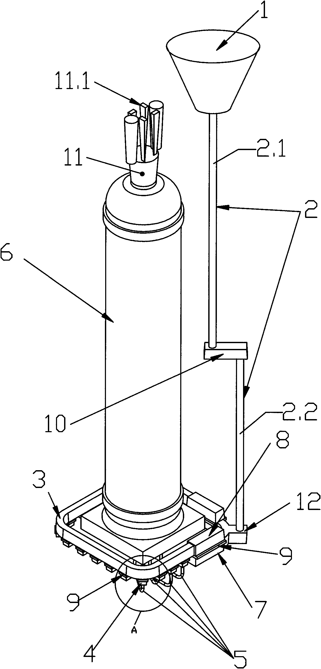
[0029] refer to figure 1 As shown, a pouring system for a stamping cylinder, which includes a sprue basin 1, a sprue 2, an upper runner 3, a lower runner 4, an inner sprue 5, The sand mold 6 is composed of a sand mold and a mold cavity. The sprue 2 is divided into at least two buffer sprues, and a first buffer runner 10 is arranged between adjacent buffer sprues.

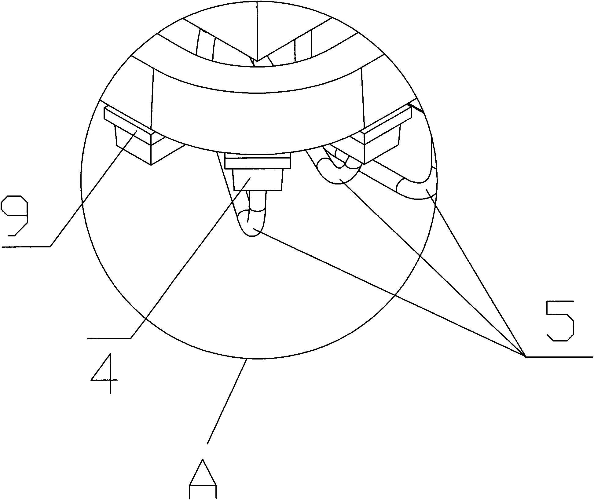
[0030] It also includes a transition upper runner 7 and a transition lower runner 8 located between the sprue 2 and the upper runner 3, and the transition upper runner 7 and the transition lower runner 8 are provided There is filter brick 9 for filtering molten iron scum.

[0031] The ingate channel 5 is a "U" elbow, and the outlet of the "U" elbow molten iron is connected to the cavity of the sand mold 6 and is arranged vertically upward.

[0032] The sprue 2 is ...


PUM


Abstract

The invention discloses a gating system for a stamping cylinder. The gating system comprises a pouring basin (1), a sprue (2), an upper cross gate (3), a lower cross gate (4), inner pouring heads (5), and a sand mold (6) which are connected sequentially along the flowing direction of molten iron; the sand mold (6) consists of a sand mould and a cavity; the sprue (2) is divided into at least two buffer sprues; and a first buffer cross gate (10) is arranged between adjacent buffer sprues. The molten iron can be poured stably, secondary oxidation caused by splashing is avoided, the molten iron scummings can be filtered, and the influence of sand removal on a casting is avoided. The gating system belongs to the technical field of casting processing.

Description

technical field [0001] The invention belongs to the technical field of casting processing, and in particular relates to a gating system of a stamping cylinder. Background technique [0002] Most of the existing stamping cylinder product castings are large-scale products with a cylindrical structure. For example, the unit weight of an existing casting is 5800Kg, the pouring weight of the casting is 8000T, the main wall thickness is about 75mm, and the maximum wall thickness is 160mm. The overall dimensions are 4485mm high x 740mm high. Therefore, the pouring weight is relatively large, and the requirements for the pouring system are relatively high, especially in terms of slag retention and exhaust. The gating system of the existing stamping cylinder includes sprue basins, sprues, upper runners, lower runners, single ingates, sand molds connected in sequence according to the direction of molten iron flow. The sand molds include sand molds and Cavity, its working process is...

Claims


Application Information

Patent Timeline
Patent Type & Authority Applications(China)
IPC IPC(8): B22C9/08B22C9/24
Inventor 马超宋贤发傅明康
Owner RIYUE HEAVY IND
Why Eureka
Try Eureka