
Rubber injection turntable

A turntable and glue injection technology, which is applied in the direction of coating, liquid coating device on the surface, etc., can solve the problems of low efficiency, glue waste, uneven pouring, etc., achieve low manufacturing cost, simple and convenient use, and improve pouring efficiency effect

Inactive Publication Date: 2013-12-25
BENGBU HONGWEI FILTER
View PDF5 Cites 9 Cited by
  • Summary
  • Abstract
  • Description
  • Claims
  • Application Information

AI Technical Summary

Problems solved by technology

In the prior art, the glue injection process of the end cap of the filter element is to pour the stirred sealing glue into the end cap of the filter element manually. Since the sealing glue should be evenly poured to the inner wall of the end cap of the filter element, the manual pouring process is not only inefficient, but also pouring Uneven, the waste of rubber is very serious

Method used


Image

  • Rubber injection turntable
  • Rubber injection turntable

Examples


Embodiment Construction

[0013] In order to make the technical means, creative features, goals and effects achieved by the present invention easy to understand, the present invention will be further described below in conjunction with specific illustrations.

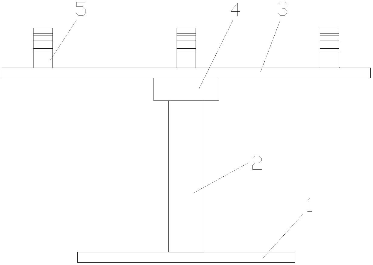
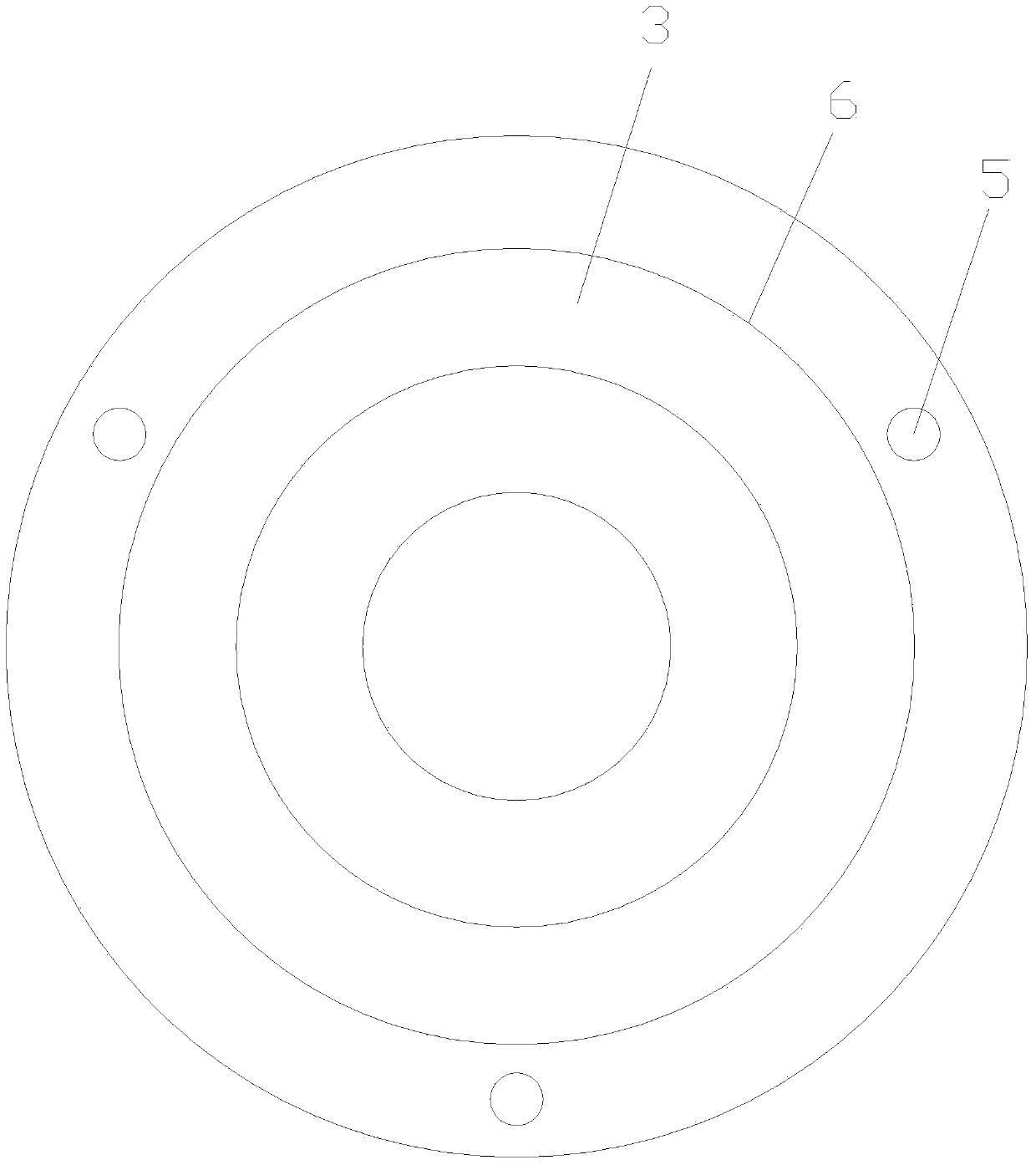
[0014] Such as figure 1 , figure 2 As shown, a glue injection turntable includes a circular chassis 1 and a circular turntable 3, the chassis 1 and the turntable 3 are connected by a vertical support shaft 2, and the upper end of the support shaft 2 is connected to the turntable 3 through a bearing 4 , the lower end of the support shaft 2 is fixedly connected with the chassis 1, the upper end of the turntable 3 is provided with three cylindrical limit blocks 5, the upper surface of the turntable 3 is provided with concentric scale marks 6, the turntable 3 is made of steel plate, and the limit block 5 is for adsorption The magnetic block at the upper end of the turntable 3, the position of the magnetic block can be placed with reference to the ...


PUM


Abstract

A rubber injection turntable relates to the field of filter production equipment and comprises a round base plate and a round turntable, wherein the base plate and the turntable are connected through a vertically arranged support shaft, the upper end of the support shaft is connected with the turntable through a bearing, the lower end of the support shaft is fixedly connected with the base plate, and three cylindrical limit blocks are arranged at the upper end of the turntable. The rubber injection turntable is simple in structure, low in manufacturing cost and simple and convenient to use, a filter element end cover is limited through a movable magnetic block, the rubber injection turntable is applicable to different specifications of the filter element end covers, a scale mark is arranged on the turntable, so that the position of the limit block is arranged according to the size of the filter element end cover, the rubber can be uniformly poured in the rotating process of the filter element end cover, and the pouring efficiency is improved.

Description

technical field [0001] The invention relates to the field of filter production equipment, in particular to a glue injection turntable used for glue injection of filter element end caps. Background technique [0002] The air filter is located in the engine intake system, and it is an assembly composed of one or several filter components that clean the air. Its main function is to filter out harmful impurities in the air that will enter the cylinder, so as to reduce the early wear of the cylinder, piston, piston ring, valve and valve seat. The dry air filter includes a dry filter element, through which the impurities in the air are separated to achieve the purpose of filtering the air. The filter material of the filter element is filter paper or non-woven fabric, and there are filter end caps at both ends of the filter element. Usually made of metal or polyurethane. During the production process of the filter, the sealing glue should be poured into the end cover of the filte...

Claims


Application Information

Patent Timeline
Patent Type & Authority Applications(China)
IPC IPC(8): B05C13/02
Inventor 陈大军何芹
Owner BENGBU HONGWEI FILTER
Learn More