Eureka AIR delivers breakthrough ideas for toughest innovation challenges, trusted by R&D personnel around the world.

Control device and control method for femto-second laser filament-forming and super-continuous radiation

A technology of supercontinuum radiation and femtosecond laser, which is applied in the field of femtosecond laser filament formation and control device of supercontinuum radiation, and can solve problems such as randomness of multifilaments

Inactive Publication Date: 2011-09-28
SHANGHAI INST OF OPTICS & FINE MECHANICS CHINESE ACAD OF SCI
View PDF2 Cites 8 Cited by
  • Summary
  • Abstract
  • Description
  • Claims
  • Application Information

AI Technical Summary

Problems solved by technology

There are also methods to control filamentation by introducing aberrations by tilting the lens or using a helical phase plate to introduce a phase difference in the wavefront, in which case the multifilaments produced between one pulse and another have good repeatability, but The position of the multifilament is essentially random

Method used


Image

  • Control device and control method for femto-second laser filament-forming and super-continuous radiation
  • Control device and control method for femto-second laser filament-forming and super-continuous radiation
  • Control device and control method for femto-second laser filament-forming and super-continuous radiation

Examples


Embodiment 1

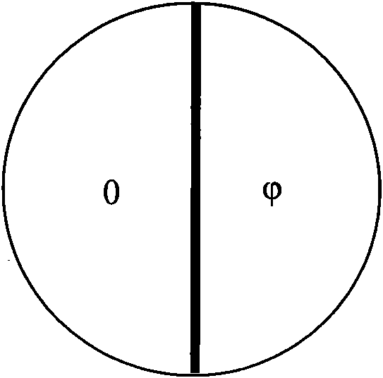
[0026] The following is an example of using a two-zone phase plate. The structure of the phase plate is as follows: figure 1 As shown, a layer of dielectric film in a semicircular area is coated on the surface of K9 glass, and the phase jump variable corresponding to the film thickness is That is, the phase plate is divided into two equal parts: the left semicircle area and the right semicircle area, which provide phase delays of 0 and π respectively. Suppose the incident light wavelength is 0.8μm, the spot is Gaussian distribution and the spot diameter is 10mm(1 / e 2 ).

[0027] After the light with a wavelength of 0.8 μm passes through the phase plate, there will be a phase difference of π between the left semicircle and the right semicircle of the light spot. After focusing with the lens, there will be two focus spots on the left and right in the focus area, and there is a phase difference of π between the two spots. Under the action of diffraction, self-focusing and pla...

Embodiment 2

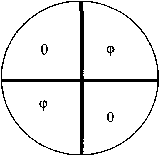
[0031] Let's continue to use a four-zone phase plate as an example. The structure of the phase plate is as follows figure 2 As shown, a circular dielectric film with four sectors is coated on the surface of K9 glass, and the phase jump variable corresponding to the film thickness is That is, the phase plate is divided into four equal parts: the upper left semicircle area, the lower left semicircle area, the upper right semicircle area and the lower right semicircle area, providing phase delays of 0, π, π, 0 respectively.

[0032] see again Figure 5 , Figure 5 It is the optical path diagram of Embodiment 2 of the femtosecond laser using four-zone phase plate to form four filaments and the supercontinuum radiation control device of the present invention;

[0033] After the light with a wavelength of 0.8 μm passes through the four-zone phase plate, the phase zone of the spot is divided into upper left semicircle, lower left semicircle, upper right semicircle, and lower ri...


PUM


Abstract

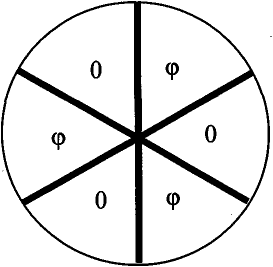
The invention discloses a control device and a control method for femto-second laser filament-forming and super-continuous radiation. The control device consists of a phase plate and a focusing lens which are sequentially arranged on an output optical path of a collimation femto-second laser, wherein the phase plate is a transmission-type phase plate or a reflection-type phase plate which has 2n spaced partitions with phase jumping quantity of pi; n is a positive integer of more than 1; and the device forms the incident femto-second laser into 2n optical filaments and then outputs the 2n optical filaments. By the invention, the accurate control of forming of the femto-second laser into a plurality of optical filaments can be realized, and the number, positions and phases of the formed filaments, and the super-continuous radiation along with filament-forming can be accurately controlled. The invention is characterized by simplicity and effectiveness.

Description

technical field [0001] The invention relates to a femtosecond laser, in particular to a control device and control method for femtosecond laser filamentation and supercontinuum radiation, which is of great significance to the application research related to femtosecond laser transmission and supercontinuum radiation. Background technique [0002] The transmission and interaction of femtosecond lasers in optical media is an important frontier field in modern physics. When the femtosecond laser exceeds the so-called critical power, when the ultra-intense femtosecond laser pulse is transmitted in the air, due to the dynamic balance of the non-linear Kerr self-focusing effect and the defocusing effect of the generated plasma, the laser is in a transparent optical medium With self-guided transmission, the distribution of laser pulses in time and space is relatively stable, forming a long plasma channel called a filament. When the incident femtosecond laser power exceeds several ...

Claims


Application Information

Patent Timeline
IPC IPC(8): G02F1/35G02B5/30
Inventor 王琛刘力程亚徐至展
Owner SHANGHAI INST OF OPTICS & FINE MECHANICS CHINESE ACAD OF SCI
Why Eureka
Eureka Blog
Learn More