
Double-shell heat exchanger

A technology of heat exchanger and double shell, applied in the direction of heat exchanger type, heat exchanger shell, indirect heat exchanger, etc., can solve problems such as heat exchanger leakage, prevent impact and wear, reduce thermal pollution, Effect of preventing deformation of sealing parts or cracking of welds

Active Publication Date: 2012-11-14
SHANDONG BEICHEN MECHANICAL & ELECTRICAL EQUIP
View PDF0 Cites 3 Cited by
  • Summary
  • Abstract
  • Description
  • Claims
  • Application Information

AI Technical Summary

Problems solved by technology

[0004] In order to overcome the defects of the existing heat exchangers due to the deformation of the sealing parts or the cracking of the weld seam caused by the temperature difference stress, the present invention provides a double-shell heat exchanger, which can prevent When the temperature difference between cold and hot media is large, the leakage of the heat exchanger will occur due to the deformation of the sealing part or the crack of the weld seam caused by the stress of the temperature difference, and the application range of the heat exchanger will be improved.

Method used


Image

  • Double-shell heat exchanger
  • Double-shell heat exchanger
  • Double-shell heat exchanger

Examples


Embodiment 1

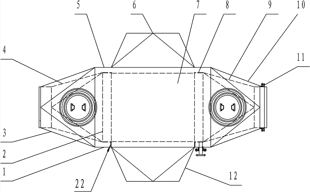
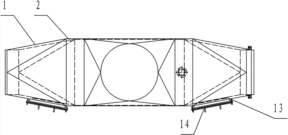
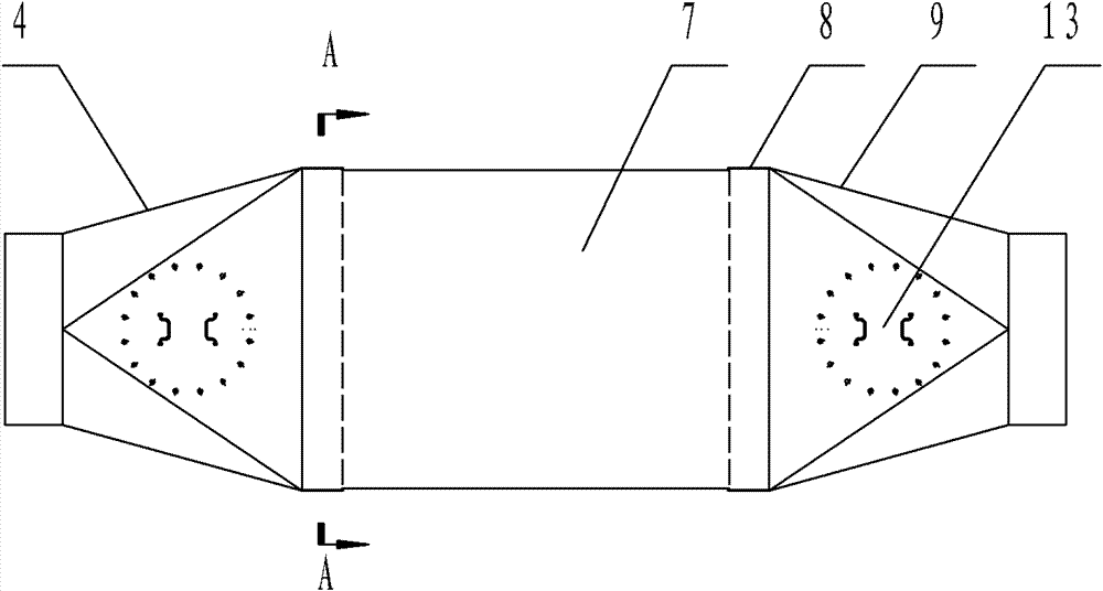
[0031] Example 1, such as figure 1 , 2 A double-shell heat exchanger is shown, which is characterized by: a refrigerant inlet outer layer reducer 3, a rectangular outer box 5, a heat medium inlet reducer 6, a heat medium outlet reducer 12, and a refrigerant outlet outer The outer casing 1 composed of layer reducing heads 10 is equipped with an inner casing 2 composed of a refrigerant inlet inner layer reducing head 4, a rectangular inner box body 8, and a refrigerant outlet inner layer reducing head 9. The outer casing and the inner casing have one end Fixed connection, the other end is connected by stuffing box sealing device 11, and the heat exchange element is installed in the rectangular inner box, and the heat exchange element is a fully welded heat exchange plate bundle or welded by multiple heat exchange tubes and tube sheets heat exchange tube bundle. The length direction of the heat exchange element is consistent with the length direction of the inner casing. The in...

Embodiment 2

[0032] Embodiment 2, a double-shell heat exchanger, is characterized in that: a refrigerant inlet outer layer reducer 3, a rectangular outer box 5, a heat medium inlet reducer 6, a heat medium outlet reducer 12, a refrigerant The outer casing 1 composed of the outlet outer layer reducing head 10 is equipped with the inner casing 2 composed of the refrigerant inlet inner layer reducing head 4, the rectangular inner box body 8, and the refrigerant outlet inner layer reducing head 9. The outer casing and the inner casing One end of the body is fixedly connected, and the other end is connected by a stuffing box sealing device 11. A heat exchange element is installed in the rectangular inner box, and the heat exchange element is a fully welded heat exchange plate welded by a plurality of heat exchange plates 15. The length direction of the heat exchange element is consistent with the length direction of the inner casing, and the surface of the inner casing facing the inlet and outle...

Embodiment 3

[0033] Example 3, such as Figure 9 A double-shell heat exchanger is shown, which is characterized by: a refrigerant inlet outer layer reducer 3, a rectangular outer box 5, a heat medium inlet reducer 6, a heat medium outlet reducer 12, and a refrigerant outlet outer The outer casing 1 composed of layer reducing heads 10 is equipped with an inner casing 2 composed of a refrigerant inlet inner layer reducing head 4, a rectangular inner box body 8, and a refrigerant outlet inner layer reducing head 9. The outer casing and the inner casing have one end Fixed connection, the other end is connected by a stuffing box sealing device 11, and a shell flange 19 is arranged on the outer shell. A heat exchange element is installed in the inner box, and the heat exchange element is a heat exchange tube bundle welded by a plurality of heat exchange tubes 16 and a tube sheet 17, and the length direction of the heat exchange element is consistent with the length direction of the inner shell. ...


PUM


Abstract

The invention discloses a double-shell heat exchanger, belonging to a heat exchanging device, and is particular suitable for a heat exchanger two sides of which are participated in heat transfer and have greater medium temperature differences; the double-shell heat exchanger is characterized in that an outer shell is internally provided with an inner shell, wherein the outer shell is composed of a refrigerant inlet outer layer variable diameter head, a rectangular outer box body, a heating medium inlet variable diameter head, a heating medium outlet variable diameter head and a refrigerant outlet outer layer variable diameter head; the inner shell is composed of a refrigerant inlet inner layer variable diameter head, a rectangular inner box body and a refrigerant outlet inner layer variable diameter head; the outer shell is fixedly connected with one end of the inner shell; the other end of the inner shell is connected through a stuffing box seal device; the inner box body is internally provided with a heat exchanging element; the surface of the inner box body facing the inlets and outlets of the refrigerant and the heating medium is not provided with a box wall; the width of the inner box body is approximate with the width of the outer box body; and two ends of the bottom surface of the inner box body are provided with a short-circuit-proof supporting plate. By the heat exchanger, the phenomenon of leakage of the heat exchanger caused by the deformation of a seal component or cracking of welding because of temperature difference stress can be prevented when the temperature difference of the refrigerant and the heating medium is great, and the scope of application of the heat exchanger is improved.

Description

technical field [0001] The invention belongs to heat exchanging equipment, and is especially suitable for heat exchangers with large temperature difference between media on both sides participating in heat exchanging. Background technique [0002] With the development of science and technology, while heat exchangers are becoming more and more diversified, their working conditions are becoming more and more harsh, such as the temperature difference between the cold and hot side media is getting larger and larger, and most of the current heat exchangers are single The shell structure, the cylinder of the plate and shell side is connected to the cold and hot medium sealing isolation parts (such as toothed plate or tube plate) at the same time, the heat exchanger due to the temperature difference between the cold and hot media, the sealing isolation parts will be Thermal stress is generated, and at the same time, thermal expansion and contraction of the plate and shell-side cyli...

Claims


Application Information

Patent Timeline
Patent Type & Authority Patents(China)
IPC IPC(8): F28D7/00F28F9/00
Inventor 徐吉田李本远杨朋
Owner SHANDONG BEICHEN MECHANICAL & ELECTRICAL EQUIP
Learn More