
Vertical axis wind driven generator with balanced torque

A technology of wind power generator and torque balance, which is applied to wind power generators, wind power motor combinations, wind power generators at right angles to the wind direction, etc. It can solve the problems of wind power generator power generation efficiency decline, blade 4 rotation failure, and blade 4 speed reduction, etc. , to achieve the effect of enhanced power generation, smooth rotation and high power generation efficiency

Inactive Publication Date: 2011-09-28
DONGFANG TURBINE CO LTD
View PDF4 Cites 7 Cited by
  • Summary
  • Abstract
  • Description
  • Claims
  • Application Information

AI Technical Summary

Problems solved by technology

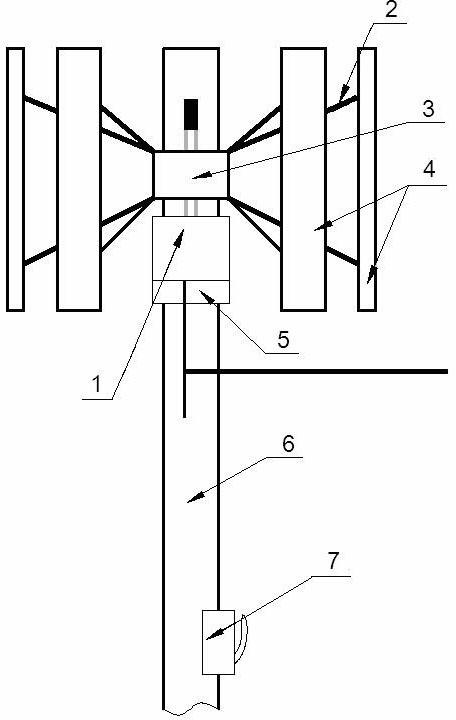
[0004] In order to capture more wind energy, vertical axis wind turbines generally adopt multiple sets of blades 4 on the hub 3 to improve efficiency, but there is a problem: since the rotation directions of these blades 4 are in the same direction, the installation position of the hub 3 Generates a torque in one direction, and the torque is not balanced
However, this will often increase the cost too much, which is not conducive to manufacturers
At the same time, due to the same direction rotation of the blade 4 and the one-way rotation of the hub 3, an asymmetric airflow will be generated around the blade 4, and a lateral thrust will be generated on the blade 4, so that the design windward surface of the blade 4 is different from the actual windward surface of the blade 4. A certain angle is generated, which affects the rotation of the blade 4, reduces the speed of the blade 4, reduces the power generation efficiency of the wind turbine, and even causes the rotation of the blade 4 to fail.

Method used


Image

  • Vertical axis wind driven generator with balanced torque
  • Vertical axis wind driven generator with balanced torque
  • Vertical axis wind driven generator with balanced torque

Examples


Embodiment Construction

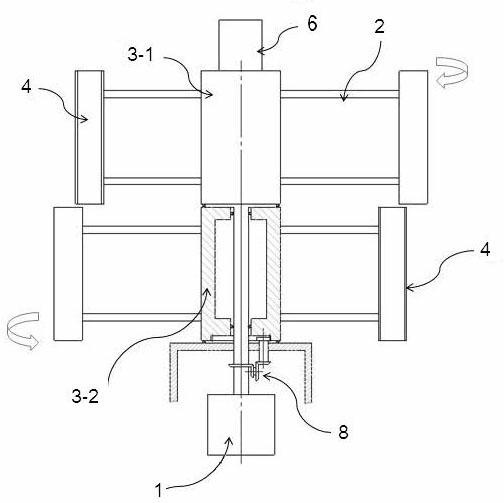
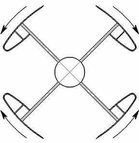
[0020] Such as Figure 2 ~ Figure 4 As shown, the present invention is a torque-balanced vertical-axis wind power generator, which includes a column 6 , multi-stage impellers and a generator 1 . The impeller consists of a hub 3, connecting rods 2 and blades 4. The hub 3 is axially and vertically arranged on the column 6, that is, the hub 3 is arranged horizontally perpendicular to the column 6. The outer peripheral surface of the hub 3 is connected by several connecting rods 2. Several groups of blades 4 . The hub 3 is connected to the main shaft of the generator 1, and the motion state of the impeller is transmitted to the power generator 1, so that the main shaft of the generator 1 rotates, thereby doing work to generate electric energy.

[0021] The multi-stage impellers of the wind power generator can be divided into two types: forward impellers and counter-rotating impellers according to the direction of rotation. The forward rotation and reverse rotation are relative t...


PUM


Abstract

The invention provides a vertical axis wind driven generator with a balanced torque. The wind driven generator comprises a vertical column, impellors and a generator, wherein the impellor is axially and vertically arranged on the vertical column through a hub; the hub drives the main shaft of the generator; the hub is provided with a plurality of blades through connecting rods; the wind driven generator is provided with multiple stages of impellors which are classified into corotational impellors and couterrotational impellors; the rotation direction of the corotational impellors is the same as that of the main shaft of the generator; the hub is directly connected with the main shaft of the generator; the rotation direction of the couterroational impellor is opposite to the that of the main shaft of the generator; and the hub is connected with the main shaft of the generator through a synchronous reverse driving mechanism. According to the invention, two torques which are reversal and counteract mutually are generated uniformly on the vertical column, thus the stability is higher for the vertical axis wind driven generator in operation, the structure rigidity is ensured, and the possibility of device damage is reduced; and simultaneously, the generation efficiency is higher, the blades rotate smoothly, the structure is simple, the practical applicability is high, and the wind driven generator is easy to use and popularize in bulk.

Description

technical field [0001] The patented technology of the invention belongs to the technical field of clean energy, and is a structural form for vertical wind power generators. Background technique [0002] Energy is a problem faced by all mankind at present. Traditional energy sources are gradually decreasing and can no longer meet people's needs. What's more, thermal power, oil, natural gas, etc. have caused great damage to the environment. Therefore, it is quite urgent to develop new clean energy sources. Among them, wind power generation is a kind of clean energy in the future, and people pay more and more attention to it. [0003] Such as figure 1 Shown is the basic structural form of the vertical axis wind power generator in the prior art, which mainly includes the generator 1 arranged on the column 6, the impeller and its braking system 5 . The impeller includes a hub 3 and blades 4 , the hub 3 is axially arranged in the direction of the column 6 , and the outer periph...

Claims


Application Information

Patent Timeline
Patent Type & Authority Applications(China)
IPC IPC(8): F03D9/00F03D3/06
CPCY02E10/74Y02E10/72
Inventor 刘平邓良廖晖宋聚众王斌沈雨虹
Owner DONGFANG TURBINE CO LTD
Learn More