
Strip-shaped jacketed oil-heat roller

A technology of oil heating rollers and jackets, applied in printing, rotary printing machines, printing machines, etc., can solve problems such as temperature difference on the surface of the roller, large temperature difference on the surface of the roller, affecting the quality consistency of drying or cooling treatment, etc. Achieve the effects of fast replacement speed, small heat loss, and small storage capacity of media

Active Publication Date: 2011-09-21
泰州科世茂工程设备有限公司
View PDF6 Cites 13 Cited by
  • Summary
  • Abstract
  • Description
  • Claims
  • Application Information

AI Technical Summary

Problems solved by technology

However, there are still some structural defects in the existing technology, that is, the heat exchange medium is injected from one end and then discharged from the other end. The flow length of the medium is proportional to the heat energy decline. There is a temperature difference on the surface of the roller, usually around 30°C
Excessive temperature difference on the surface of the roller will inevitably affect the consistency of the quality of the conveyed fabric in drying or cooling treatment

Method used


Image

  • Strip-shaped jacketed oil-heat roller
  • Strip-shaped jacketed oil-heat roller
  • Strip-shaped jacketed oil-heat roller

Examples


Embodiment Construction

[0015] The present invention will be further described below according to the accompanying drawings and in conjunction with the embodiments.

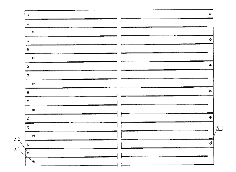
[0016] figure 1 The shown strip jacket oil heating roller includes inner pipe 1, input shaft 2, end cover 3, separator 4, inner cylinder 5, outer cylinder 6, slats 7, inner ring plate 8, ventilation pipe 9. Support shaft 10 and connecting pipe 11. The input shaft 2 is a hollow shaft structure located at the left end, the support shaft 10 is a solid shaft structure located at the right end, and the two ends of the connecting pipe 11 are coaxially fixedly connected to the input shaft 2 and the support shaft 10 respectively. The inner cylinder 5 and the outer cylinder 6 are both cylindrical thin-walled cylinders, and the inner cylinder 5 and the outer cylinder 6 with different diameters fit together to form a jacket structure. The inner wall is fixedly connected with the inner ring plate 8 in the axial direction. The end cover 3 is prov...


PUM


Abstract

The invention discloses a strip-shaped jacketed oil-heat roller, which comprises an inner pipe, an input shaft, an end cover, a partition plate, an inner cylinder, an outer cylinder, a strip, an inner ring plate, a ventilating pipe, a supporting shaft and a connecting pipe, wherein the input shaft is a hollow shaft, the jointing end of the input shaft and the connecting pipe is provided with a left radial hole and a right radial hole, and the inner pipe is inserted into the inner hole of the input shaft and connected with a step by crossing the left radial hole to form a bidirectional independent channel. The jointing end of the supporting shaft and the connecting pipe is provided with an axial blind hole channel which is communicated with the radial holes. The inner cylinder is connectedwith the input shaft and the supporting shaft through the inner ring plate, the baffle plate and the end cover; and a strip-shaped groove consisting of the strip is arranged in a jacket between the inner cylinder and the outer cylinder, and is communicated with an oil inlet cavity, an oil return cavity and the bidirectional independent channel through oil inlets at two ends of the wall of the inner cylinder and an oil return hole at one end of the wall of the inner cylinder. The strip-shaped jacketed oil-heat roller ensures that the error of a temperature on the surface of the roller is less than 5 DEG C through bidirectional equivalent heat exchange, thereby improving product quality. The invention is suitable for being matched with various specifications of rollers.

Description

technical field [0001] The invention relates to a roller used in a printing machine, in particular to a strip-shaped jacketed oil heating roller with high heat exchange efficiency. Background technique [0002] The oil heating roller is a heat exchange device that directly contacts the cloth in the printing machine, and its heat exchange structure determines the heat exchange efficiency. The traditional oil heating roller is a cylindrical container. The heat exchange medium is injected from one end and then discharged from the other end. The built-in medium displaces external heat through the outer wall. The heat exchange structure is very simple and can realize effective heat exchange. Chinese Patent No. 200420080372.1 discloses a jacketed roller. This technology adopts a jacket structure, which effectively reduces the inner volume of the roller, speeds up the replacement of the medium, reduces heat energy loss, and improves heat exchange efficiency. However, there are st...

Claims


Application Information

Patent Timeline
Patent Type & Authority Applications(China)
IPC IPC(8): B41F13/08B41F17/38
Inventor 袁恒凤胡如琴
Owner 泰州科世茂工程设备有限公司
Learn More