Anti-vibration damper for coil spring
A coil spring and damper technology, applied in springs/shock absorbers, coil springs, mechanical equipment, etc., to achieve the effects of improving assembly performance, suppressing sliding noise, and reducing contact area
- Summary
- Abstract
- Description
- Claims
- Application Information
AI Technical Summary
Problems solved by technology
Method used
Image
Examples
no. 1 approach
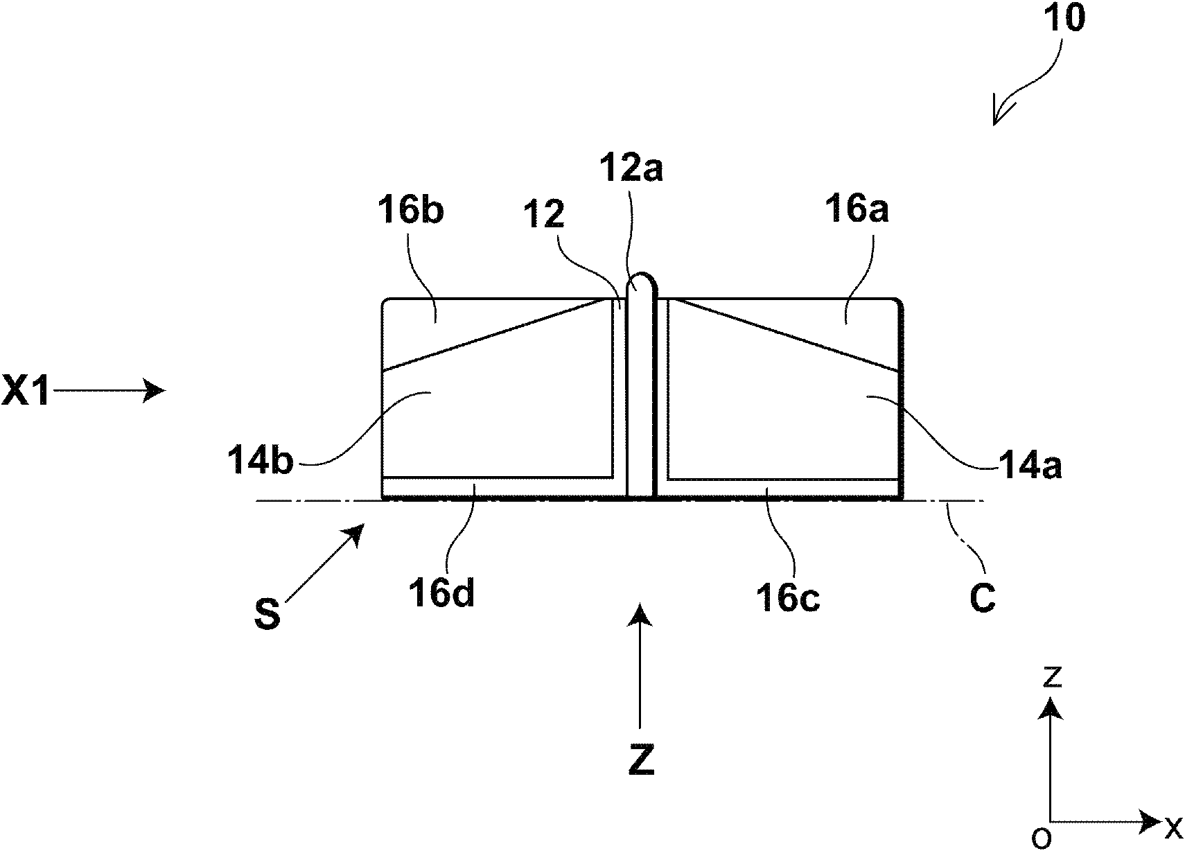
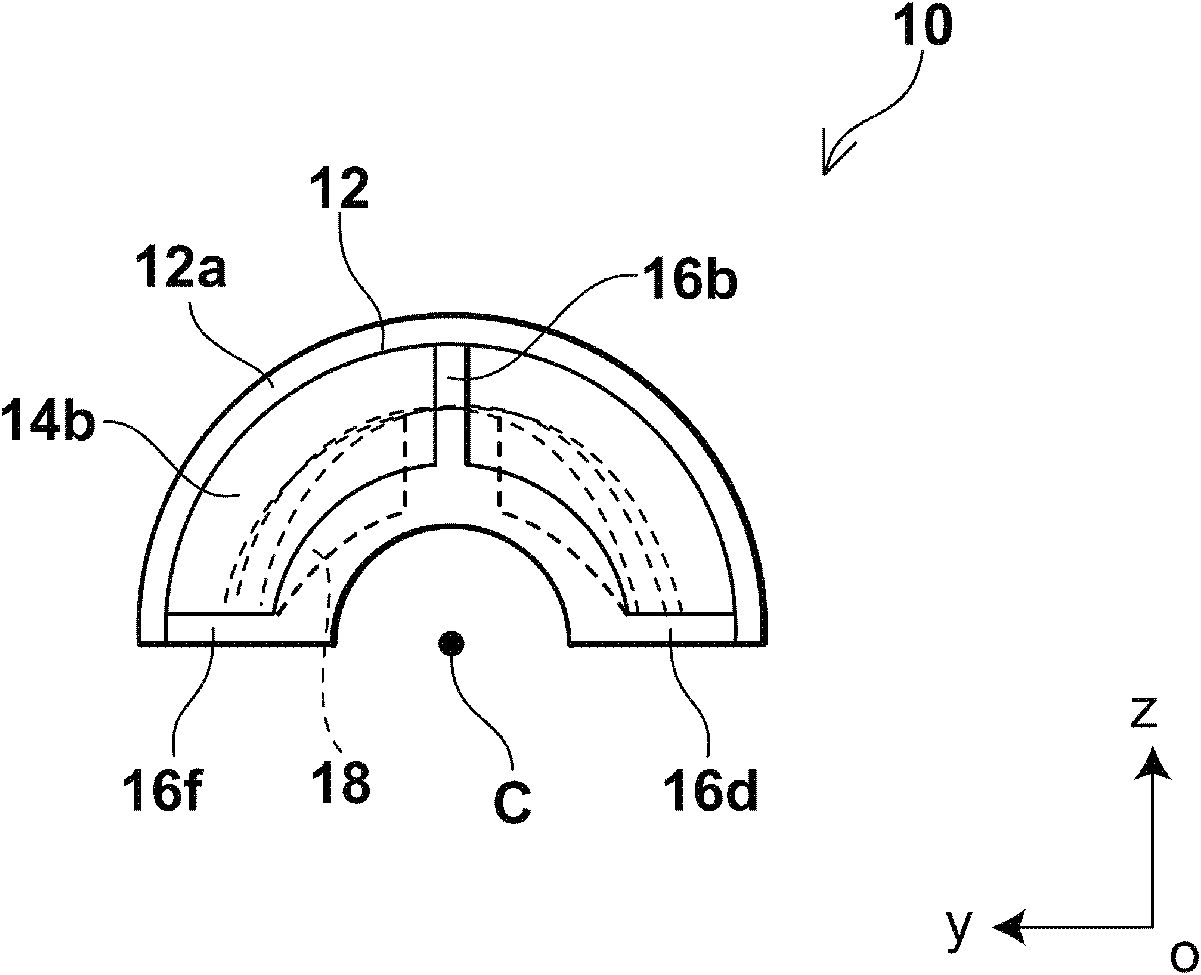
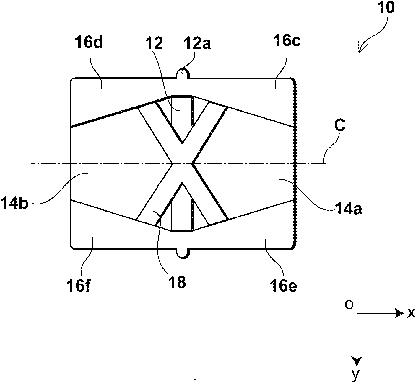
[0050] First, the following will refer to Figures 1 to 4 The anti-vibration damper according to the first embodiment of the present invention will be described in detail.
[0051] figure 1 It is a side view of the anti-vibration damper of this embodiment. figure 2 is a front view of the anti-vibration damper of this embodiment, and shows along figure 1 The view obtained by the arrow in X1. image 3 is a bottom view of the anti-vibration damper of this embodiment, and shows along figure 1 The view obtained by the arrow Z in . in addition, Figure 4 is a bottom perspective view of the anti-vibration damper of this embodiment, and shows the figure 1 The view obtained by the arrow S in .
[0052] Such as Figures 1 to 4 As shown, the anti-vibration damper 10 is a cylindrical member extending along an axis C parallel to the x-axis and having a peripheral wall portion partially cut along the negative direction of the z-axis. Here, the anti-vibration damper 10 includes a c...
no. 2 approach
[0086] Next, further reference Figure 10 with Figure 11 An anti-vibration damper according to a second embodiment of the present invention will be described in detail.
[0087] Figure 10 is a front view of the anti-vibration damper of the current embodiment, and is in positional relationship with figure 2 corresponding to that shown. and, Figure 11 is a bottom perspective view of the anti-vibration damper of the current embodiment, and is in positional relationship with Figure 4 corresponding to that shown.
[0088] Such as Figure 10 with Figure 11 As shown, the main difference between the anti-vibration damper 50 of the present embodiment and the anti-vibration damper 10 of the first embodiment is that the first rib 56a, the third rib 56c and the fifth rib 56e of the first extension 14a And the second rib 56b, the fourth rib 56d and the sixth rib 56f of the second extension part 14b are changed in shape, and the rest of the structure remains the same. Therefo...
no. 3 approach
[0092] Next, further reference Figure 12 to Figure 15 An anti-vibration damper according to a third embodiment of the present invention will be described in detail.
[0093] Figure 12 is a side view of the anti-vibration damper according to the present embodiment. Figure 13 is a front view of the anti-vibration damper of this embodiment, and shows along Figure 12 The view obtained by the arrow in X1. Figure 14 is a bottom view of the anti-vibration damper of this embodiment, and shows along Figure 12 The view obtained by the arrow Z in . and, Figure 15 is a bottom perspective view of the anti-vibration damper of this embodiment, and shows the Figure 12 The view obtained by the arrow S in .
[0094] Such as Figure 12 to Figure 15 As shown, the main difference between the anti-vibration damper of this embodiment and the anti-vibration damper of the first embodiment lies in the shape changes of the central part 62, the first extension part 64a and the second exte...
PUM
 Abstract
Description
Claims
Application Information
 - R&D
- Intellectual Property
- Life Sciences
- Materials
- Tech Scout
- Unparalleled Data Quality
- Higher Quality Content
- 60% Fewer Hallucinations
Browse by: Latest US Patents, China's latest patents, Technical Efficacy Thesaurus, Application Domain, Technology Topic, Popular Technical Reports.
© 2025 PatSnap. All rights reserved.Legal|Privacy policy|Modern Slavery Act Transparency Statement|Sitemap|About US| Contact US: help@patsnap.com


