
110KV intermediate head and production process thereof

A technology for intermediate joints and production processes, which is applied in the direction of cable joints, connections, electrical components, etc., can solve problems such as inability to directly inspect with the naked eye, difficult pressure control, low yield, etc., to achieve visual inspection, easy inspection, high visibility effect

Active Publication Date: 2011-09-14
江苏远航电缆附件有限公司
View PDF5 Cites 10 Cited by
  • Summary
  • Abstract
  • Description
  • Claims
  • Application Information

AI Technical Summary

Problems solved by technology

[0003] One is to install the stress cone, shielding tube and outer shielding layer at the fixed position of the insulating silicone rubber mold before injecting insulating silicone rubber. Because the outer shielding layer is relatively thin and bulky, it is easy to deform during installation and difficult to assemble; when injecting silicone rubber The pressure is difficult to control, and the pressure control is not good. There are problems such as glue passing and outer shielding layer being squeezed and deformed. Although this process can be produced, the yield is not high, and the process parameters are difficult to control.
[0004] The second is that the insulating part of the existing intermediate joint is made of colored opaque insulating silicone rubber, while the stress cone, shielding tube and outer shielding layer are made of black opaque conductive silicone rubber. When injecting insulating silicone rubber, there may be volume Larger impurities are brought into the insulating silicone rubber. After vulcanization and molding, the insulating part is wrapped by the outer shielding layer, which cannot be inspected directly with the naked eye. If there are too many impurities in the insulating silicone rubber, it will have a serious impact on the electrical properties of the rubber. Sometimes it will cause partial discharge, which will affect the service life of the intermediate joint, and in severe cases, it will directly break down

Method used


Image

  • 110KV intermediate head and production process thereof
  • 110KV intermediate head and production process thereof
  • 110KV intermediate head and production process thereof

Examples


Embodiment Construction

[0031] The present invention will be further described below in conjunction with the accompanying drawings and embodiments.

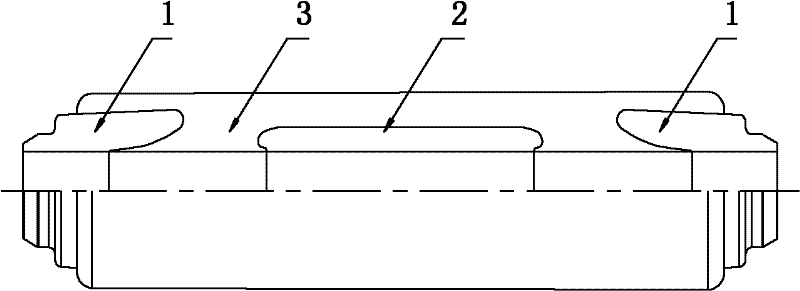
[0032] Such as figure 1 As shown, in the production process of an intermediate joint above 110KV, the requirements for the production environment are relatively strict. If it is produced in an ordinary environment, the dust in the air will pollute the rubber body, because the product is injection molded multiple times and installed in the mold. When the parts are directly exposed to the air, the surface of the mold and the rubber body will be contaminated with dust in the air, and the glue will be mixed in the liquid rubber when it is injected, and it will stay in the rubber body after vulcanization, especially the insulating silicone rubber. The silicone rubber body contains too many impurities, which will seriously affect the electrical properties of the rubber, cause partial discharge, and affect the service life of the intermediate joint. In serious...


PUM


Abstract

The invention provides an 110KV intermediate head and a production process thereof. The intermediate head comprises two stress cones (1), a screening tube (2), insulating layers (3) and outer screening layers (4), wherein the screening tube (2) is arranged between the two stress cones (1); the insulating layers (3) are filled between the screening tube (2) and the two stress cones (1); and the outer screening layers (4) are coated outside the insulating layers (3). The process of producing the 110KV intermediate head comprises three formations, that is, the first formation is the formation ofthe conductive stress cones and the screening tube; the second formation is the formation of the insulating layers: the formed stress cones and a formed stress tube are arranged in a mould during glue injection and then integrated after formation; and the third formation is the formation of outer conducting layers: all parts are integrated after formation to form the intermediate head. The formedinsulating layers of the intermediate head are made from transparent insulated rubbers, thus being high in visibility and being convenient to check.

Description

technical field [0001] The invention relates to a production process of an intermediate joint, and in particular specifies the production flow and production method of a 110KV intermediate joint. Background technique [0002] The cable intermediate joint is used as the conductor, insulation shielding layer and protective layer connecting the cable and the cable to connect the cable line. Usually, the cable intermediate joint has a stress cone, a shielding tube, an insulating layer and an outer shielding layer. The stress cone, shielding tube and outer shielding layer are made of conductive silicone rubber, and the insulating layer is made of insulating silicone rubber, which is molded by multiple injections of silicone rubber; The existing production process is to produce the stress cone, shielding tube and outer shielding layer first, and then inject insulating silicone rubber, which is integrated with the stress cone, shielding tube and outer shielding layer; there are two...

Claims


Application Information

Patent Timeline
IPC IPC(8): H02G15/18H02G15/188H01R43/00
Inventor 夏兰夏晴
Owner 江苏远航电缆附件有限公司
Learn More