


Quick Research
Generate reliable direction feasibility study reports for your R&D in just a few steps.

Technical Q&A
Discover and master advanced knowledge NOW. Basics, ideas, possibilities, all at once.

Find Solutions
As an expert in R&D theories, this can generate solutions to your technical problems instantly.

Evaluate Feasibility
Analyze your overall solution with one click, know your potential R&D risks in advance.

Monitor Landscape
Get weekly tech updates, stay abreast of the latest tech innovations and key insights.
Sensor element with improved air inlet
A technology of sensor elements and air intake holes, which is applied in the direction of instruments, scientific instruments, and material analysis through electromagnetic means, and can solve problems such as increasing diffusion resistance, blocking diffusion barriers, and fouling
- Summary
- Abstract
- Description
- Claims
- Application Information
AI Technical Summary
Problems solved by technology
Method used
Image

Examples
Embodiment Construction
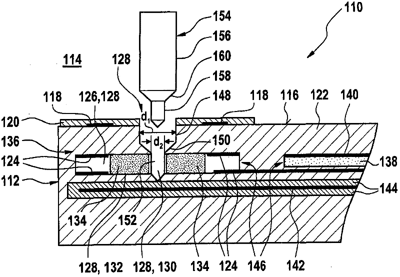
[0032] exist figure 1 A first exemplary embodiment of a sensor element 110 according to the invention is shown in . An exemplary embodiment of the production method according to the invention of such a sensor element 110 should also be explained with the aid of this schematic diagram. The sensor element 110 has a layer structure 112 which can be produced using ceramic thin-film methods and / or thick-film methods. Layer structure 112 includes a surface 116 facing measurement gas chamber 114 , on which surface 116 a first electrode 118 is arranged. exist figure 1 In the exemplary embodiment shown, the first electrode 118 can, for example, be configured as a ring, because figure 1 The sensor element 110 in may mostly have a rotationally symmetrical structure. However, other configurations are also conceivable. First electrode 118 is separated from measurement gas chamber 114 , for example, by a gas-permeable protective layer 120 . Furthermore, layer structure 112 has one or ...
PUM
 Abstract
Description
Claims
Application Information
 - R&D Engineer
- R&D Manager
- IP Professional
- Industry Leading Data Capabilities
- Powerful AI technology
- Patent DNA Extraction
Browse by: Latest US Patents, China's latest patents, Technical Efficacy Thesaurus, Application Domain, Technology Topic, Popular Technical Reports.
© 2024 PatSnap. All rights reserved.Legal|Privacy policy|Modern Slavery Act Transparency Statement|Sitemap|About US| Contact US: help@patsnap.com