Self-driven balancing machine rotating component and corresponding tire balancing machine
A rotating component, self-driving technology, used in static/dynamic balance testing, machine/structural component testing, measuring devices, etc., can solve problems such as transmission error, inconvenient manufacturing, complex structure, etc., to achieve sensitive balance detection, Accurate and efficient detection
- Summary
- Abstract
- Description
- Claims
- Application Information
AI Technical Summary
Problems solved by technology
Method used
Image


Examples
Embodiment approach 1
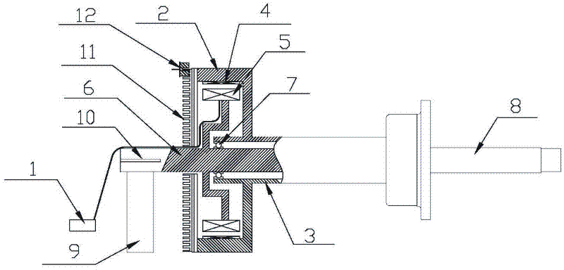
[0021] Implementation mode one: if figure 1 , 2 As shown, the self-driven balancing machine rotating assembly includes an outer rotor, an inner stator, a position sensor and a control circuit 1, and the outer rotor and the inner stator are fixed on the same axis. The outer rotor includes a cylindrical casing 2 and a rotor bushing 3. A plurality of permanent magnet blocks 4 are evenly attached to the inner wall of the cylindrical casing 2. The front edge of the cylindrical casing 2 is fixedly connected with the rotor bushing 3. The inner stator includes a stator coil 5 and the stator shaft 6, the front part of the stator shaft 6 is inserted into the rotor sleeve 3, and a bearing 7 is arranged between them.
[0022] The corresponding tire balancing machine includes a main shaft 8, a motor and a balance detection system, the balance detection system includes a piezoelectric sensor module 9 that can sense the vibration of the main shaft 8, and the motor includes a rotating assemb...
Embodiment approach 2
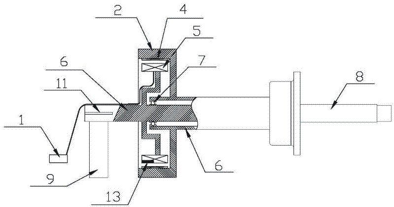
[0025] Implementation mode two: if image 3 , 4 As shown: the self-driven balancing machine rotating assembly includes an outer rotor, an inner stator, a position sensor and a control circuit 1, and the outer rotor and the inner stator are fixed on the same axis. The outer rotor includes a cylindrical shell 2 and a rotor shaft 14, a plurality of permanent magnet blocks 4 are evenly attached to the inner wall of the cylindrical shell 2, the rear edge of the cylindrical shell 2 is fixedly connected with the rotor shaft 14, and the inner stator includes a stator coil 5 and The stator shaft sleeve 15, the rotor shaft 14 passes through the stator shaft sleeve 15, and the bearing 7 is arranged between them.
[0026] The corresponding tire balancing machine includes a main shaft 8, a motor and a balance detection system, the balance detection system includes a piezoelectric sensor module 9 that can sense the vibration of the main shaft 8, and the motor includes a rotating assembly, ...
PUM
 Abstract
Description
Claims
Application Information
 - Generate Ideas
- Intellectual Property
- Life Sciences
- Materials
- Tech Scout
- Unparalleled Data Quality
- Higher Quality Content
- 60% Fewer Hallucinations
Browse by: Latest US Patents, China's latest patents, Technical Efficacy Thesaurus, Application Domain, Technology Topic, Popular Technical Reports.
© 2025 PatSnap. All rights reserved.Legal|Privacy policy|Modern Slavery Act Transparency Statement|Sitemap|About US| Contact US: help@patsnap.com