Power door lock bolt driving device

A driving device and lock tongue technology, applied in the field of locks, can solve the problems of poor reliability and complex structure, and achieve the effects of simple driving, small size and reliable action

Active Publication Date: 2012-11-07
NANJING EASTHOUSE ELECTRIC CO LTD
View PDF5 Cites 0 Cited by
  • Summary
  • Abstract
  • Description
  • Claims
  • Application Information

AI Technical Summary

Problems solved by technology

[0003] The purpose of the present invention is to design an electric door lock bolt drive device for controlling the opening of locks that is suitable for use in various safes in view of the problems of complex structures or poor reliability of locks used in existing safes

Method used


Image

  • Power door lock bolt driving device
  • Power door lock bolt driving device
  • Power door lock bolt driving device

Examples


Embodiment Construction

[0022] The present invention will be further described below in conjunction with the accompanying drawings and embodiments.

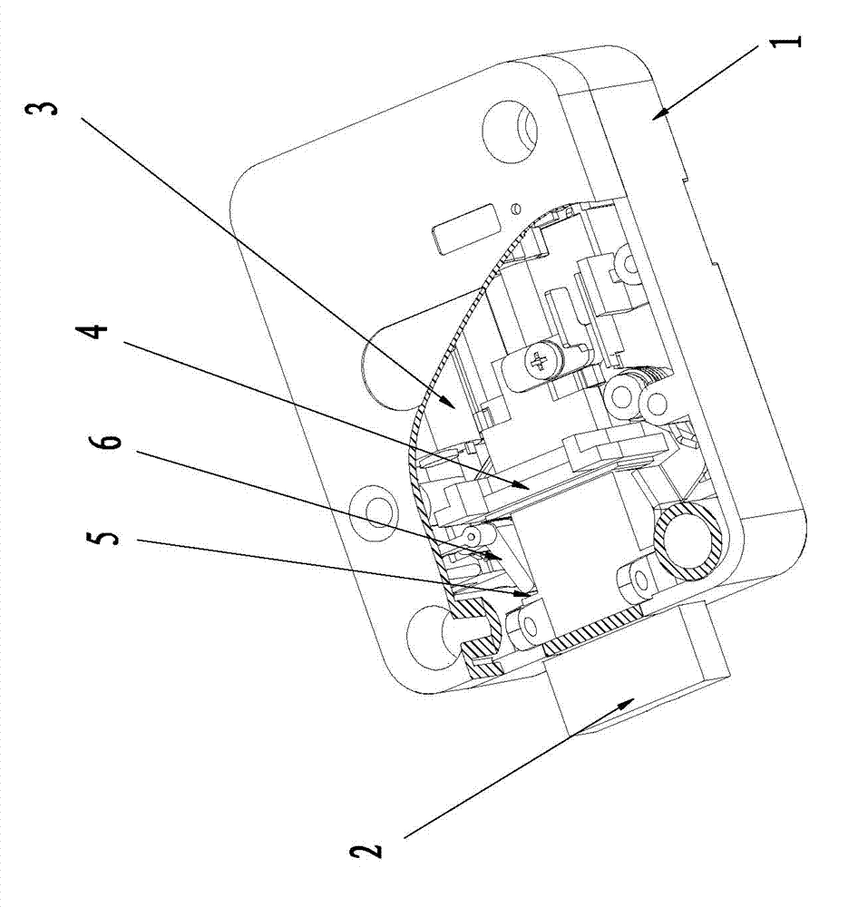
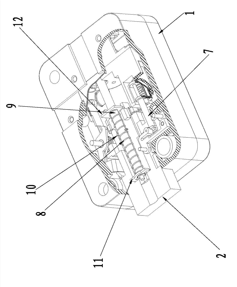
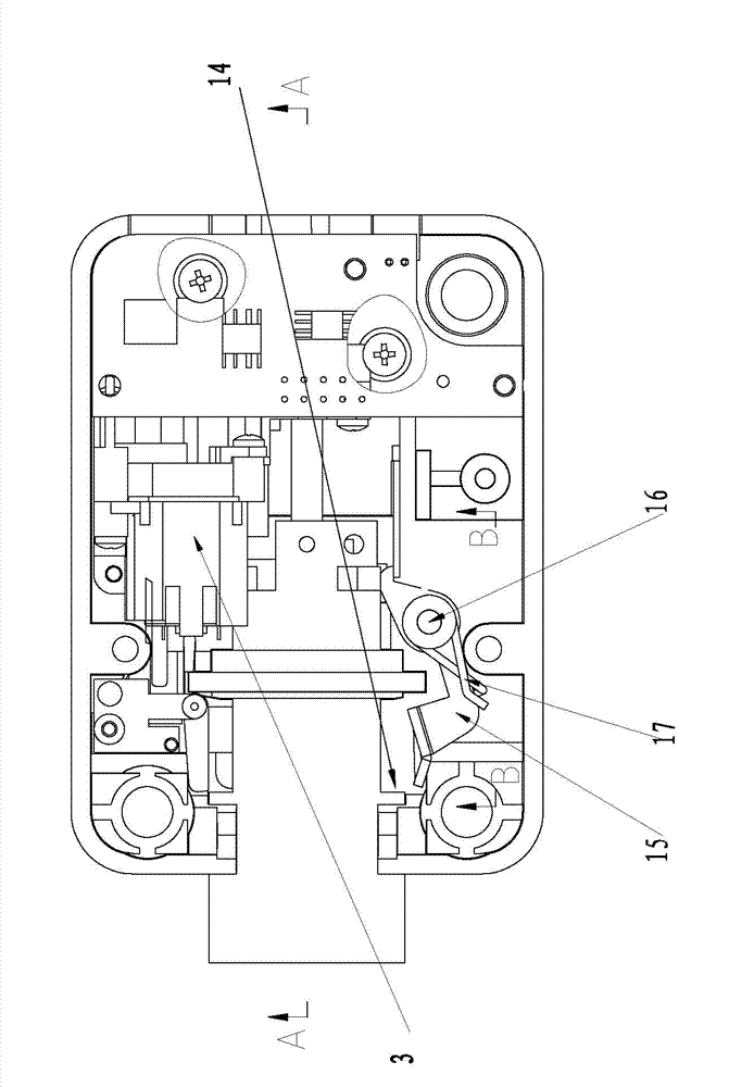
[0023] like Figure 1-6 shown.

[0024] An electric door lock bolt driving device, which includes a driving motor 24, the output shaft of the driving motor 24 is connected with the input shaft of the reduction box 3, and the reduction box 3 is provided with two output shafts, wherein the first output shaft 20 is connected to the first drive shaft 7 through the first drive device 25 installed thereon, and the first drive shaft 7 is opposite to one side of the lock pendulum 6 so as to drive the lock pendulum 6 to realize locking and unlocking of the dead bolt. The other side of the anti-swing block 6 is opposite to the anti-retreat step 5 on the deadbolt 2; the second output shaft 9 of the reduction box 3 is connected with the deadbolt 2 through the second driving device 26 and drives the deadbolt 2 to move in the guide mechanism 4 , the guide mecha...


PUM


Abstract

The invention relates to an electric door lock bolt driving device which comprises a driving motor (24). The electric door lock bolt driving device is characterized in that an output shaft of the driving motor (24) is connected with an input shaft of a reduction gearbox (3), the reduction gearbox (3) is provided with two output shafts, a first output shaft (20) is connected with a first driving shaft (7) by a first driving device (25) arranged on the first output shaft, the first driving shaft (7) is opposite to one side of a locking oscillating block (6) so as to drive the locking oscillating block (6) to lock and unlock a bolt, and the other side of the locking oscillating block (6) is opposite to a retreating stop step (5) on the bolt (2); and a second output shaft (9) of the reductiongearbox (3) is connected with the bolt (2) by a second driving device (26) and drives the bolt (2) to move in a guide mechanism (4). The electric door lock bolt driving device has a simple structure,and is reliable in action, good in anti-prizing performance, low in energy consumption, and long in service life.

Description

technical field [0001] The invention relates to a lock, in particular to an electronic lock used on a bank cash box or a gun cabinet, in particular to an electric door lock bolt driving device. Background technique [0002] At present, the lock structure of various safes such as fingerprint safes and password safes generally adopts a motor-driven ratchet mechanism, a block driving mechanism and a connecting rod driving mechanism to realize automatic unlocking. Among them, the ratchet mechanism is relatively complicated, and it is inconvenient to process, install, and maintain. At the same time, its volume is relatively large, occupying a large effective space in the safe, and there are also problems in the structure of the dial drive mechanism and the connecting rod drive mechanism. Simultaneously, they also have a common problem, that is, the reliability is poor, and the movement of the shifting block will not be in place and the cabinet door cannot be opened. For this re...

Claims


Application Information

Patent Timeline
Patent Type & Authority Patents(China)
IPC IPC(8): E05B47/00E05B15/00E05B15/10E05B65/52
Inventor 闵浩
Owner NANJING EASTHOUSE ELECTRIC CO LTD
Why Eureka
Try Eureka