
Pneumatic device for machining deep ring slots on inner cylindrical surface

An inner cylindrical, pneumatic technology, applied in the direction of drive devices, metal processing equipment, metal processing machinery parts, etc., can solve the problems that deep ring grooves cannot be machined, mechanical processing cannot be realized, and radial cutting cannot be realized, etc.

Inactive Publication Date: 2013-05-22
XI AN JIAOTONG UNIV
View PDF5 Cites 0 Cited by
  • Summary
  • Abstract
  • Description
  • Claims
  • Application Information

AI Technical Summary

Problems solved by technology

The entire inner cylindrical surface can be machined by machining, but the deep ring groove on the small-diameter inner cylindrical surface away from the shaft end surface cannot be machined
This is because the diameter of the inner cylindrical hole is too small, and the cutting tool in the prior art cannot realize the radial feed (feed) movement, thus the requirements for machining cannot be realized.

Method used


Image

  • Pneumatic device for machining deep ring slots on inner cylindrical surface

Examples


Embodiment Construction

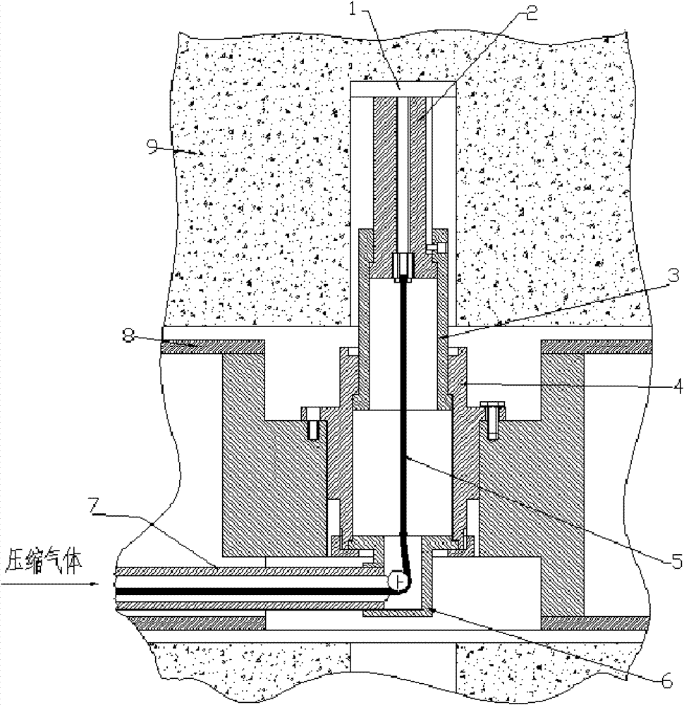
[0013] Shown with reference to accompanying drawing, device of the present invention is mainly made of parts such as cutter 1, telescopic knife rest 2,3, knife rest seat 4, steel rope 5 and elbow 6, gas conduit 7.

[0014] Tool 1 is a forming knife with the same width as the ring groove.

[0015] Cutter 1 is contained on the telescopic knife rest 2, and telescopic knife rest 2 and 3 are contained in the knife rest seat 4, and elbow 6 and gas conduit 7 are affixed with knife rest seat 4. One end of steel wire rope 5 is affixed to cutter, and the other end passes through gas conduit 7 and joins with servo motor (not shown in the figure).

[0016] The telescopic knife rest 2 can slide in the telescopic knife rest 3 , and the telescopic knife rest 3 can move axially along the knife rest seat 4 . The tensioning and loosening of the wire rope 5 are controlled by a servo motor. A certain amount of compressed air is required for work.

[0017] This device is placed in the steel pip...


PUM


Abstract

The invention discloses a pneumatic device for machining deep ring slots on an inner cylindrical surface. The device comprises a tool, first and second telescopic tool rests, a tool rest bracket, a wire rope, a bend and a gas conduit, wherein the tool is arranged on the first telescopic tool rest; the first and second telescopic tool rests are arranged in the tool rest bracket; the bend and the gas conduit are fixedly connected with the tool rest bracket; one end of the wire rope is fixedly connected with the tool, while the other end passes through the gas conduit to connect a servomotor. Inthe device, a multi-stage telescopic tool rest structure is adopted, a mode of combining a flexible component and a rigid component is adopted, the rigid component of the tool completes a cutting action, the flexible component of the wire rope is used for control, and a mode of combining machinery and air drive is adopted during machining. The wire rope controls the tool to feed, compressed air drives the tool to move, and the tool moves with the telescopic tool rest in a mechanical mode.

Description

technical field [0001] The invention relates to special processing in the fields of machine manufacturing and aerospace, in particular to a pneumatic device for processing deep ring grooves on the inner cylindrical surface. Background technique [0002] In engineering, it is required to process deep ring grooves on the surface of inner cylindrical workpieces with small diameters of non-metallic materials, and the position of deep ring grooves is far away from the end surface of the workpiece shaft. [0003] Existing technology can't solve it. It has been proposed to use the method of model forming to realize it, but it cannot be realized due to the particularity of the workpiece material and the limitation of the model forming method. In addition, due to the particularity of the industry, there are currently no relevant literature and ready-made technologies at home and abroad for reference and reference. As a last resort, the only solution currently available is to change...

Claims


Application Information

Patent Timeline
Patent Type & Authority Patents(China)
IPC IPC(8): B23C3/34B23Q5/027
Inventor 陈钢庞宣明陈晓南
Owner XI AN JIAOTONG UNIV
Learn More