Miniature electromagnetic type vibration energy collector and manufacturing method thereof

An energy harvester, electromagnetic vibration technology

Inactive Publication Date: 2013-11-13
SHANGHAI INST OF MICROSYSTEM & INFORMATION TECH CHINESE ACAD OF SCI
View PDF0 Cites 0 Cited by
  • Summary
  • Abstract
  • Description
  • Claims
  • Application Information

AI Technical Summary

Problems solved by technology

[0004] The existing reported electromagnetic energy harvesters still have relatively large deficiencies in terms of device volume, efficiency, and integration with sensors due to the processing technology mostly adopting assembly technology or adhesion methods, such as Peihong Wang et al. in "A micro electromagnetic low level Vibration energy harvester based on MEMS technology” (Microsystem technologies, 2009, Vol.15, 941~951) reported an electromagnetic energy harvester, which is composed of planar springs, permanent magnets, Composed of microcoils and supporting structures, it is difficult to bond and fix the permanent magnet and the metal platform in the center of the planar spring, and the permanent magnet cannot be positioned precisely
In addition, the assembly of the support structure and the substrate is also a difficult point
In the article "Microelectromechanical systems vibration powered electromagnetic generator for wireless sensor application" (Microsystem technologies, 2006, Vol.12, 1071-1077), E. Koukharenko et al proposed an electromagnetic energy harvester with a sandwich structure, with two upper and lower layers It is a permanent magnet, the middle layer is a silicon platform vibrating horizontally, and a metal coil is embedded in the center of the silicon platform. Although the energy harvester is made of silicon material, its natural frequency is very large, so it is difficult to be applied in the actual environment.
[0005] According to the above, the electromagnetic energy harvesters reported in the prior art have shortcomings such as large volume, poor manufacturing precision, and poor stability. In addition, most of the mechanical vibrations in the environment are low-frequency vibrations. In order to overcome these shortcomings and Strive to achieve practical application, the present invention intends to propose a low-frequency micro-electromagnetic vibration energy harvester based on silicon materials. The energy harvester has the advantages of small size, simple manufacturing method, easy batch manufacturing, and good stability. broad

Method used


Image

  • Miniature electromagnetic type vibration energy collector and manufacturing method thereof
  • Miniature electromagnetic type vibration energy collector and manufacturing method thereof
  • Miniature electromagnetic type vibration energy collector and manufacturing method thereof

Examples


Embodiment

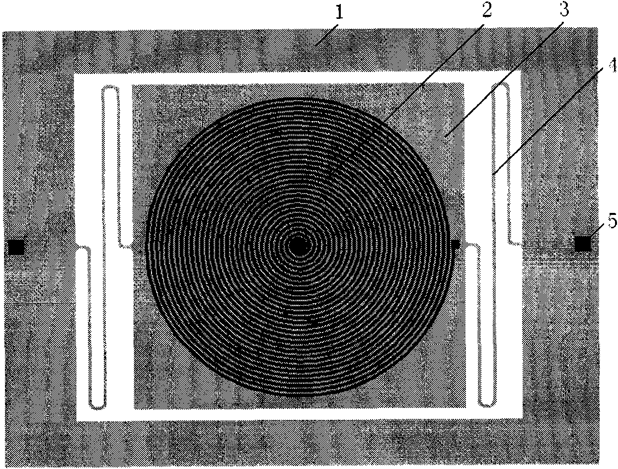
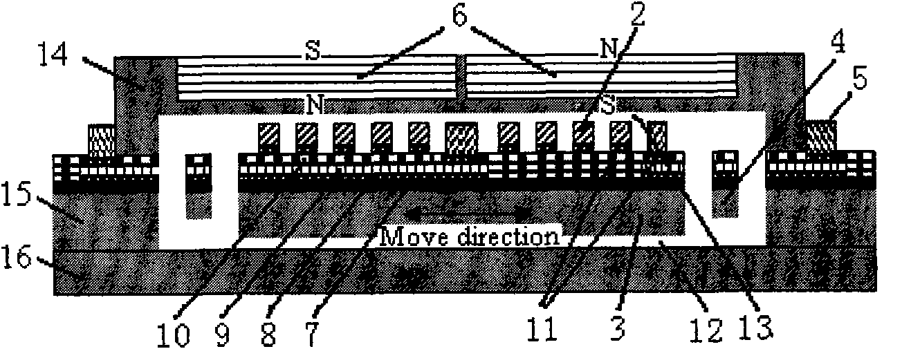
[0038] Embodiments of the present invention relate to energy harvester structures, combined with the attached figure 1 and 2 illustrate.

[0039] The top view of the structure of the energy harvester (without the upper cover and permanent magnet) is as follows figure 1 As shown, it mainly includes an external support frame 1, a planar spiral coil 2, electrodes 5, a central mass 3, and a folded elastic beam 4. The planar helical coil 2 is fabricated on the upper surface of the central mass 3 , and the central mass 3 is connected to the external support frame 1 through two folded elastic beams 4 . The structural section of the energy harvester is shown in figure 2 As shown, it mainly includes an upper cover silicon wafer 14, two permanent magnets 6, a vibration structure silicon wafer 15, and a substrate silicon wafer 16. Two permanent magnets 6 are placed side by side in the pits on the upper surface of the upper cover silicon wafer 14, and the directions of the magnetic p...


PUM

PropertyMeasurementUnit
thicknessaaaaaaaaaa
thicknessaaaaaaaaaa
thicknessaaaaaaaaaa

Abstract

The invention relates to a miniature electromagnetic type vibration energy collector and a manufacturing method thereof. The electromagnetic type vibration energy collector consists of a centre mass block, an outer support frame, two folded elastic beams, a plane spiral coil, two permanent magnets, an upper cover plate, a substrate and the like. In the electromagnetic type vibration energy collector, vibration structures (including the centre mass block and the folded elastic beams) are manufactured by using bulk silicon micromachine processing technique, the plane spiral coil is manufactured by using a surface micromachine processing technique and is manufactured on the upper surface of the centre mass block; and the two permanent magnets are located above the plane spiral coil in parallel. The energy absorber can work in a low frequency range, and mechanical energy vibrated in the environment is converted into electrical energy, thereby solving the problem that a wireless sense network or micro-nano device and the like depend on a battery to achieve supply feed. The energy absorber has the advantages of small volume, simple manufacturing method, wide application prospect and the like, and is easy to produce in batches.

Description

technical field [0001] The invention relates to a miniature electromagnetic vibration energy collector for collecting vibration energy in the environment and a manufacturing method thereof. The energy collector is prepared by a micro-processing method combining bulk silicon and surface micromachines, and belongs to the field of micro-electromechanical systems. Background technique [0002] The development of micro-nano technology has greatly promoted the emergence of a large number of new micro-nano devices and systems, and has also largely promoted the development of micro wireless sensor networks and communication nodes. However, whether it is wireless sensing products or micro-nano Devices, their volume is continuously reduced, power consumption is gradually reduced, and the problem of power supply is becoming an obstacle to their development. Currently, chemical energy batteries, rechargeable batteries or fuel cells are used as electrical energy sources, although the effi...

Claims


Application Information

Patent Timeline
Patent Type & Authority Patents(China)
IPC IPC(8): H02K35/04B81C1/00
Inventor 李伟车录锋王鹏王跃林
Owner SHANGHAI INST OF MICROSYSTEM & INFORMATION TECH CHINESE ACAD OF SCI
Why Eureka
Try Eureka