Steel wire hanging frame and construction method thereof
A cable hanger and steel cable technology, which is applied to the hanger of equipment pipelines in large-space workshops or computer rooms and their construction fields, can solve the problems of unsuitable large-space workshops or computer rooms, complicated structure of pipeline hangers and large loads, etc. The effect of saving material, flexible choice and increasing stability
- Summary
- Abstract
- Description
- Claims
- Application Information
AI Technical Summary
Problems solved by technology
Method used
Image
Examples
Embodiment 1
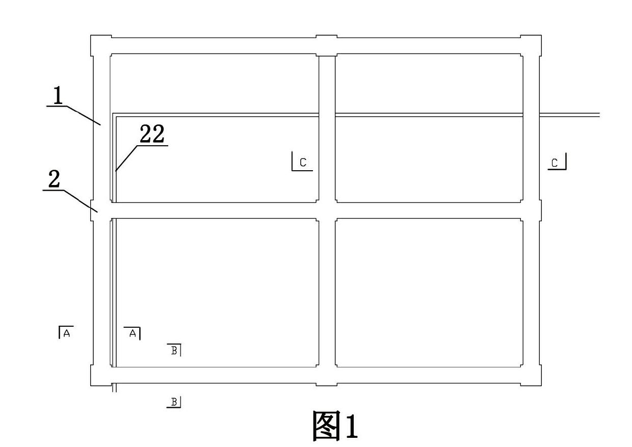
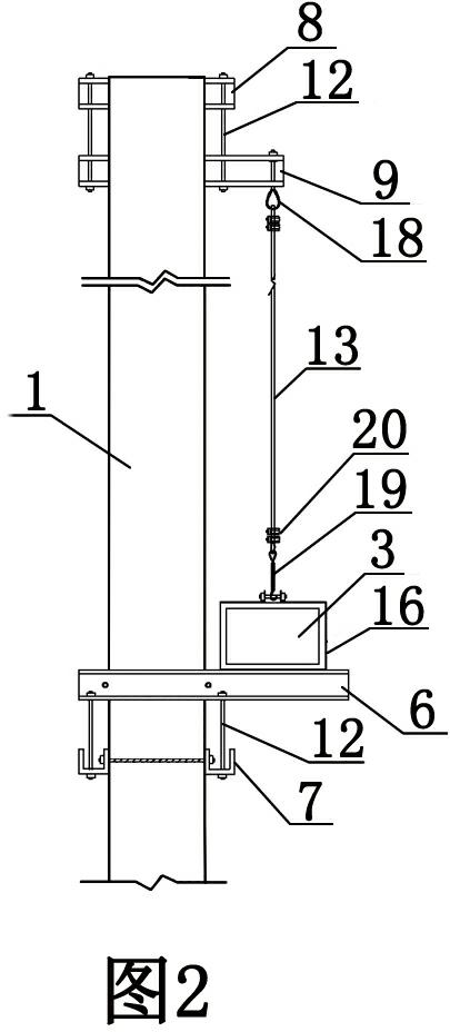
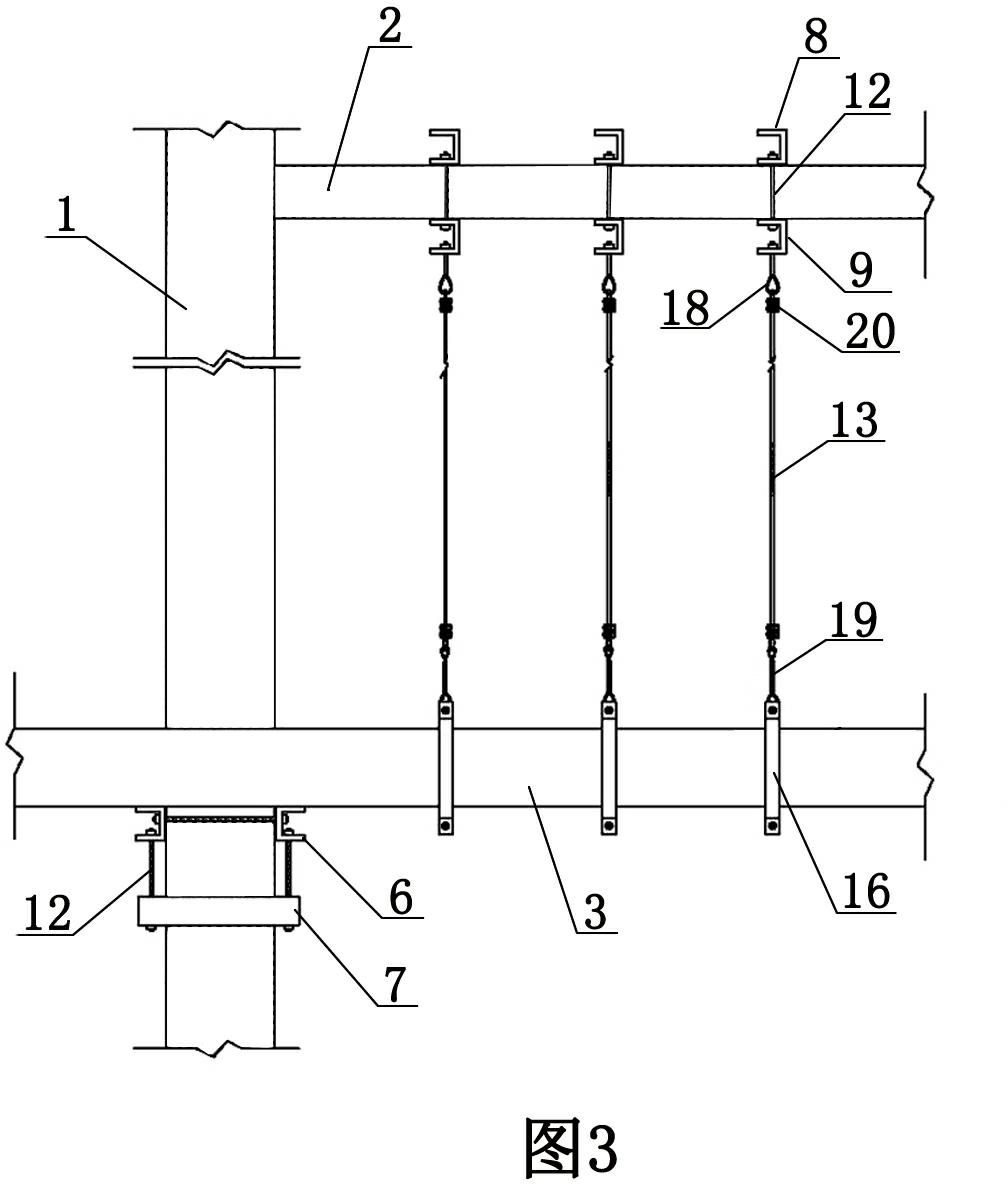
[0047] Embodiment one sees Figure 1-5 As shown: this kind of cable hanger is composed of two parts: the cable hanger at the position adjacent to the equipment pipeline 22 and the column 1, and the cable hanger at the position where the equipment pipeline 22 is far away from the column 1, and the column 1 is in the shape of a square Arranged at intervals, the beams 2 are vertically and horizontally connected between the columns 1 .
[0048] The steel cable hanger of described equipment pipeline 22 and column 1 adjacent positions comprises: column hoop support, beam hoop support 1, equipment pipeline connector and vertical steel cable 13; 6. The lower cross arms 7 of the two columns are connected by the tension bolts 12; It is connected with the lower cross arms 7 of the two columns by vertical tension bolts 12, and one end of the upper cross arms 6 of the two columns is extended to the outside of the column 1 and supported at the bottom of the equipment pipeline 22; the beam ...
Embodiment 2
[0052] Embodiment two, see Figure 6-9 As shown, when the equipment pipeline 22 is a ventilation duct or a bridge frame 4, the equipment pipeline connector adopts the lower horizontal platform 17 of the equipment pipeline, and the lower horizontal platform 17 of the equipment pipeline is laterally supported on the bottom of the equipment pipeline 22. The vertical steel cable 13 is connected between the two ends of the lower horizontal arm 17 of the equipment pipeline and the lower horizontal arm I of the beam; two beam hoop brackets II are respectively connected on the beams 2 parallel to each other, and the cable-stayed steel cable 14 is connected to the two Between the lower cross arm II of the beam hoop support II and the two ends of the corresponding lower horizontal tanks 17 of each equipment pipeline below; the horizontal steel cable 15 is connected between the lower horizontal tanks 17 of each equipment pipeline.
[0053] The upper ends of the vertical steel cables 13 a...
Embodiment 3
[0054] Embodiment three, see Figure 10-13 As shown, when the equipment pipeline 22 is a water pipe 5 , the equipment pipeline connector adopts the lower horizontal tank 17 of the equipment pipeline, and the lower horizontal tank 17 of the equipment pipeline is laterally supported on the bottom of the equipment pipeline 22 . The vertical steel cable 13 is connected between the two ends of the lower horizontal arm 17 of the equipment pipeline and the lower horizontal arm I of the beam; two beam hoop brackets II are respectively connected on the beams 2 parallel to each other, and the cable-stayed steel cable 14 is connected to the two Between the lower cross arm II of the beam hoop support II and the two ends of the corresponding lower horizontal tanks 17 of each equipment pipeline below; the horizontal steel cable 15 is connected between the lower horizontal tanks 17 of each equipment pipeline.
[0055] The water pipe 5 is connected with an inverted U-shaped water pipe hoop 21...
PUM
 Abstract
Description
Claims
Application Information
 - R&D
- Intellectual Property
- Life Sciences
- Materials
- Tech Scout
- Unparalleled Data Quality
- Higher Quality Content
- 60% Fewer Hallucinations
Browse by: Latest US Patents, China's latest patents, Technical Efficacy Thesaurus, Application Domain, Technology Topic, Popular Technical Reports.
© 2025 PatSnap. All rights reserved.Legal|Privacy policy|Modern Slavery Act Transparency Statement|Sitemap|About US| Contact US: help@patsnap.com


