
Control method of EGR (exhaust gas recirculation) control system of engine

A control system and control method technology, applied in the direction of engine control, machine/engine, mechanical equipment, etc., can solve the problems of engine fuel consumption increase, carbonization, coking of mixed gas, etc., and achieve the effect of improving thermal efficiency and simple structure

Active Publication Date: 2013-07-17
CHERY AUTOMOBILE CO LTD
View PDF4 Cites 0 Cited by
  • Summary
  • Abstract
  • Description
  • Claims
  • Application Information

AI Technical Summary

Problems solved by technology

[0003] Although the above method reduces the pumping loss work to a certain extent, because this part of EGR remains in the intake manifold or exhaust pipe, it will often cause the mixture to coke or even carbonize on the intake wall, resulting in increased fuel consumption of the engine. high
In addition, due to the size of the valve overlap angle, which determines the opening of the exhaust valve and the closing time of the intake valve, under different operating conditions, there is often a certain contradiction with the closing angle of the intake valve to make full use of the intake air, resulting in internal The EGR rate is not up to the optimum requirement

Method used


Image

  • Control method of EGR (exhaust gas recirculation) control system of engine
  • Control method of EGR (exhaust gas recirculation) control system of engine
  • Control method of EGR (exhaust gas recirculation) control system of engine

Examples


Embodiment 1

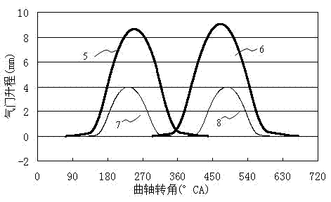
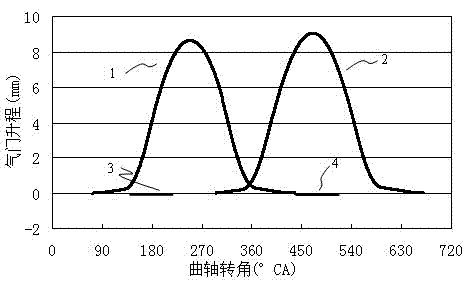
[0019] The EGR control system of the engine of this embodiment includes an electronic control unit and a valve train, and the valve train is provided with an intake valve consisting of a first intake valve and a second intake valve corresponding to each cylinder block, and an intake valve composed of a first intake valve and a second intake valve. An exhaust valve consisting of an exhaust valve and a second exhaust valve, the intake valve is controlled by an intake camshaft, the exhaust valve is controlled by an exhaust camshaft, the first intake valve, the second The intake valves are respectively controlled by two cams with different lift ranges arranged on the intake camshaft, and the first exhaust valve and the second exhaust valve are respectively controlled by two different lift ranges arranged on the exhaust camshaft. The electric control unit is connected with the engine control system, and controls the operation of the cams on the intake camshaft and exhaust camshaft t...


PUM


Abstract

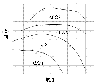
The invention provides an EGR (exhaust gas recirculation) control system of an engine and a control method thereof. The EGR control system comprises an electric control unit and a valve mechanism, wherein corresponding to each cylinder, the valve mechanism is provided with an inlet valve consisting of a first inlet valve and a second inlet valve, and an exhaust valve consisting of a first exhaustvalve and a second exhaust valve; the inlet valve is subject to control of an inlet cam shaft, and the exhaust valve is subject to an exhaust cam shaft; the first inlet valve and the second inlet valve are respectively subject to control of two cams that are arranged on the inlet cam shaft and different in lift range; the first exhaust valve and the second exhaust valve are respectively subject to control of two cams that are arranged on the exhaust cam shaft and different in lift range; and the electric control unit controls the work of the cams on the inlet cam shaft and the exhaust cam shaft through a transmission mechanism and changes valve timing and valve lift. With different loads, the electric control unit adopts different lift and phase combination ways to control the EGR rate ofresidues in the cylinder, thus improving the thermal efficiency of the engine.

Description

technical field [0001] The invention belongs to the technical field of automobile engine manufacturing, and in particular relates to an EGR control system and a control method of an engine with an exhaust gas recirculation device (EGR). Background technique [0002] Exhaust Gas Recirculation (Exhaust Gas Recirculation) refers to the technology of introducing part of the exhaust gas into the intake air for re-combustion after the internal combustion engine of an automobile is burned, which can reduce nitrogen oxides (NOx) in the exhaust gas and improve fuel economy. With the increasingly stringent emission regulations and rising fuel prices, EGR technology is more and more widely used in engines. At present, the internal EGR of the engine is mainly controlled by VVT (Variable Valve Timing) and VVL (Variable Valve lift) technologies, through late closing of the exhaust valve and early opening of the intake valve to form a certain Overlap (valve overlap angle) is used to adjus...

Claims


Application Information

Patent Timeline
Patent Type & Authority Patents(China)
IPC IPC(8): F02D13/02
Inventor 贾志超
Owner CHERY AUTOMOBILE CO LTD
Learn More