Low-voltage low-noise wideband mixer

A low-voltage, mixer technology, applied in the direction of multi-frequency modulation conversion, etc., can solve the problems of small voltage swing, difficult matching, large Gilbert mixer noise, etc., to improve noise performance and optimize high-frequency noise. , optimize the effect of switching noise

Active Publication Date: 2013-01-30
NANJING QINHENG MICROELECTRONICS CO LTD
View PDF0 Cites 0 Cited by
  • Summary
  • Abstract
  • Description
  • Claims
  • Application Information

AI Technical Summary

Problems solved by technology

[0003] The first is input matching. In the MOS process, the RF differential signal is directly connected to the gates of the transconductance unit MOS transistors Q1 and Q2. The high impedance characteristics of the gates are not conducive to matching to 50Ω, especially in broadband structure design. Matching is more difficult;
[0004] The second is noise. In the design of the mixer, the transconductance unit MOS transistors Q1 and Q2 require large currents to optimize channel noise, while the switching unit MOS transistors Q3, Q4, Q5, and Q6 require moderately small currents to reduce switching noise. noise, the two form a pair of contradictions
The method of current injection can alleviate the contradiction between the two to a certain extent, but it increases the complexity of the design, and the current injection circuit itself will inevitably introduce additional noise
Therefore, the noise of the Gilbert mixer is large, and the noise figure of the single sideband is usually greater than 9dB
[0005] The third is the working voltage. The traditional Gilbert mixer needs transconductance unit MOS transistors Q1, Q2, switching unit MOS transistors Q3, Q4, Q5, Q6 and the load to multiplex the current, and even the transconductance unit needs to add a tail Current source I EE , so traditional Gilbert mixers are not conducive to low-voltage operation, especially in deep submicron MOS processes, low voltage makes design work more difficult;
Since the transconductance unit, switch unit and load unit adopt a stacked structure to multiplex current, the drain-source voltage V of the transconductance unit MOS transistors Q1 and Q2 DS is relatively small, and the voltage swing obtained on the load is also relatively small, so the linearity of the traditional Gilbert mixer is limited

Method used


Image

  • Low-voltage low-noise wideband mixer
  • Low-voltage low-noise wideband mixer
  • Low-voltage low-noise wideband mixer

Examples


Embodiment Construction

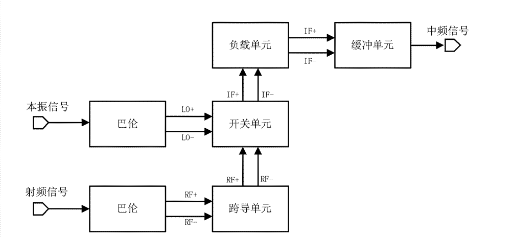
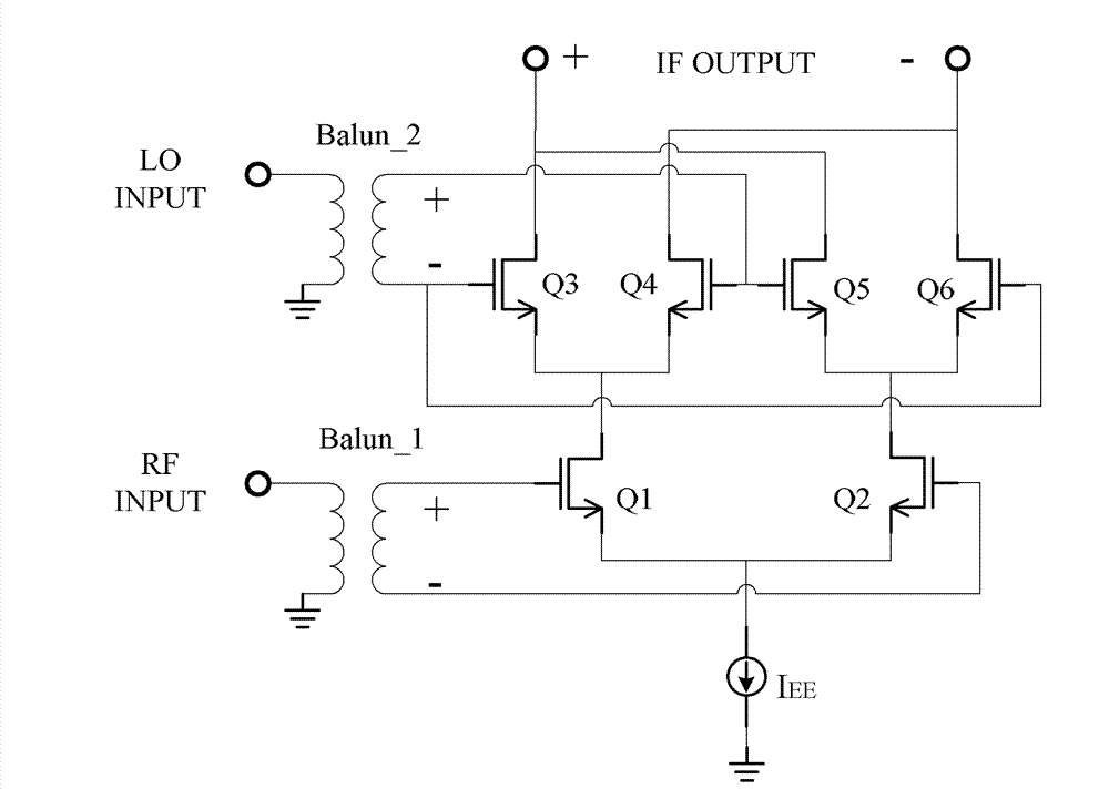
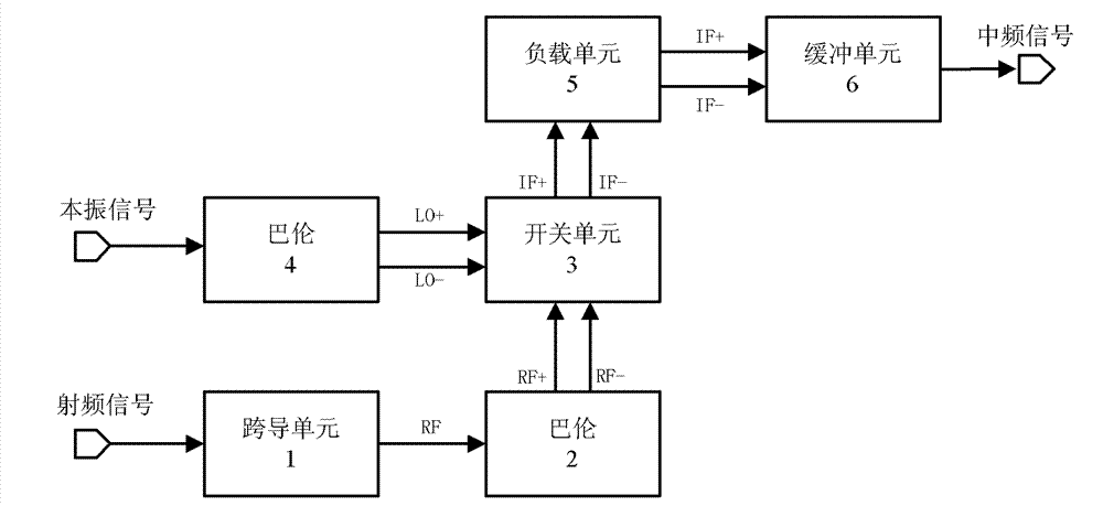
[0027] see image 3 , 4, the local oscillator signal L0 is connected to one end of the primary coil of the Balun unit circuit Balun_2, the other end of the primary coil is grounded, and the positive phase local oscillator signal terminal L0+ of the secondary coil is connected to the gates of the MOS transistors M2 and M5 of the switch unit 3, The anti-phase local oscillator signal terminal L0 of the secondary coil is connected with the gates of the MOS transistors M3 and M4 of the switch unit 3, and the center tap of the secondary coil is connected to the bias voltage Vbias2; compared with the traditional Gilbert mixer In the present invention, the single-ended input radio frequency signal RF is directly input to the transconductance unit 1 and then to the Balun Balun_1. The transconductance unit 1 adopts a common gate structure with grid series inductance (transmission lines can also be used instead of inductance), and the common grid tube M1 grid The pole series inductor L1...


PUM


Abstract

The invention discloses a low-voltage low-noise wideband mixer, which is provided with a transconductance unit, balun units, a switch unit, a load unit and a buffer unit circuit. The low-voltage low-noise wideband mixer is characterized in that: the transconductance unit adopts a cascode structure consisting of inductors of which gates are connected in series; a single-ended input radio frequency signal is directly input into the transconductance unit for amplification, and the amplified radio frequency signal is output to the balun unit and converted into a differential radio frequency signal which is output to the switch unit; a local oscillation signal is input into the other balun unit, and the single-ended signal is converted into a differential signal which is output to the switch unit; and the switch unit multiplies the differential local oscillation signal by the differential radio frequency signal to generate a differential intermediate frequency signal, and a single-ended intermediate frequency signal is output after the differential intermediate frequency signal passes through the load unit and the buffer unit circuit.

Description

technical field [0001] The invention relates to a broadband mixer, especially a low-voltage and low-noise broadband mixer, which adopts MOS technology, has great advantages in millimeter wave circuits, and has a simple design structure. While improving noise performance and linearity, the power The consumption is reduced by half, and it has a large gain bandwidth and input matching bandwidth. Background technique [0002] In 1968, Barrie Gilbert proposed the Gilbert double-balanced multiplier structure for the first time, and it was widely used in mixers (hereinafter referred to as "Gilbert mixer"). The circuit block diagram and circuit principle are as follows figure 1 , figure 2 As shown, the radio frequency signal RF converts the single-ended signal into differential signals RF+ and RF- through the balun, and connects the gates of the transconductance unit common source structure MOS transistors Q1 and Q2 respectively, and the MOS transistors Q1 and Q2 convert the input...

Claims


Application Information

Patent Timeline
Patent Type & Authority Patents(China)
IPC IPC(8): H03D7/16
Inventor 李智群曹佳李芹王志功
Owner NANJING QINHENG MICROELECTRONICS CO LTD
Why Eureka
Try Eureka