
Small-caliber aspherical composite precise processing method

A precision machining and aspheric surface technology, applied in the field of aspheric surface processing, can solve the problems of reducing processing efficiency, consuming auxiliary man-hours, and affecting processing accuracy, so as to prevent interference, reduce installation errors, and improve processing accuracy and processing efficiency.

Inactive Publication Date: 2011-08-24
HUNAN UNIV
View PDF3 Cites 21 Cited by
  • Summary
  • Abstract
  • Description
  • Claims
  • Application Information

AI Technical Summary

Problems solved by technology

The disadvantage of using the above two processes is that the workpiece needs to be clamped multiple times on two different machine tools, which will cause installation errors, tool setting errors and other consequences that affect the machining accuracy; at the same time, multiple clamping consumes more Many auxiliary man-hours reduce the processing efficiency

Method used


Image

  • Small-caliber aspherical composite precise processing method
  • Small-caliber aspherical composite precise processing method
  • Small-caliber aspherical composite precise processing method

Examples


Embodiment 1

[0029] Embodiment 1: see attached Figure 1~4 ,

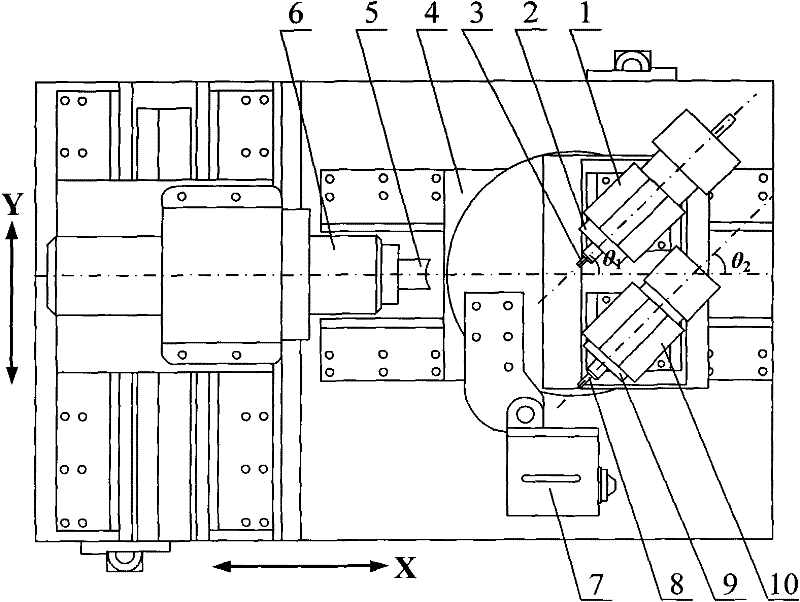
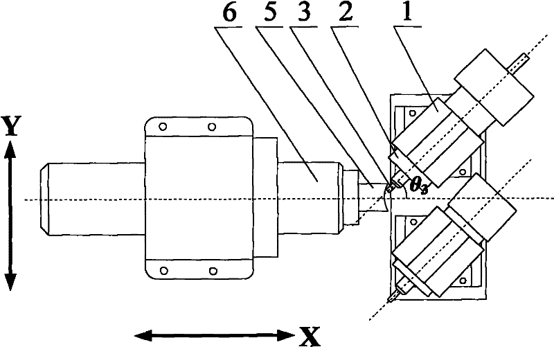
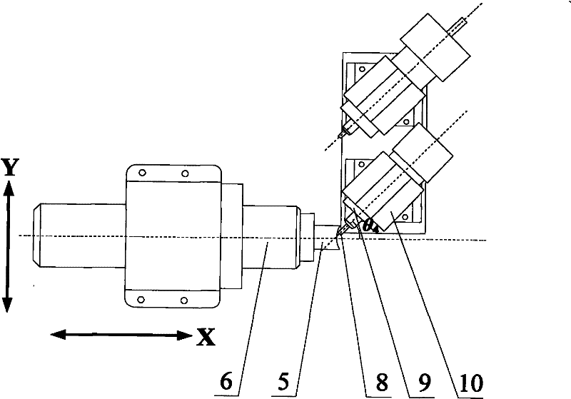
[0030] One, the workpiece 5 is clamped on a ULPG type precision machine tool manufactured by the Micro-Nano Manufacturing Research Institute of the National High-efficiency Grinding Engineering Technology Research Center of Hunan University in China, so that the grinding wheel spindle 2 axis of the oblique axis mirror grinding device 1 of the machine tool It is parallel to the axis spacing of the grinding head spindle 9 of the inclined-axis magneto-rheological polishing device 10 , and the two axes are equally spaced from the slide table 4 . The two axes and the axis of the workpiece spindle 6 successively form an equiangular angle ∠θ 1 and ∠θ 2 intersects, the ∠θ 1 and ∠θ 2 The angles are all 40°; then, the workpiece 5 and the micropowder grinding wheel 3 are centered using an optical magnifying glass. Then, the micropowder grinding wheel 3 is driven by the grinding wheel spindle 2 to perform oblique-axis grinding on the ...

Embodiment 2

[0033] Embodiment 2: see attached Figure 1~4 ,

[0034] 1. The workpiece 5 is clamped on the precision machine tool, and the axes of the grinding wheel main shaft 2 of the inclined-axis mirror grinding device 1 are parallel to the axis spacing of the grinding head main shaft 9 of the inclined-axis magnetorheological polishing device 10, and the The two axes are equally spaced from the slide table 4 . The two axes and the axis of the workpiece spindle 6 successively form an equiangular angle ∠θ 1 and ∠θ 2 intersects, the ∠θ 1 and ∠θ 2 The angles are all 50°; then, the workpiece 5 and the micropowder grinding wheel 3 are centered using an optical magnifying glass. Then, the micropowder grinding wheel 3 is driven by the grinding wheel spindle 2 to perform oblique-axis grinding on the aspherical surface of the workpiece 5 according to the set grinding track. During processing, the axis of the grinding wheel spindle 2 intersects the axis of the workpiece spindle 6 at an angl...


PUM


Abstract

The invention relates to a small-caliber aspherical composite precise processing method. The method comprises the following steps of: 1. clamping a workpiece (5) on a precise machine tool, wherein axes of a grinding wheel spindle (2) and a grinding head spindle (9) are parallel, separated from a sliding table (4) and intersected with the axis of a workpiece spindle (6); and grinding and processing an inclined shaft of the workpiece (5) by a micropowder grinding wheel (3); 2. carrying out in-place measurement on the workpiece (5) by using a detecting device (7) to generate a compensation processing track, and then processing along the track by the mocropowder grinding wheel (3); and 3. using a grinding head (8) to grind and polish the workpiece (5) to finally obtain a finished product. In the small-caliber aspherical composite precise processing method, precise inclined axis mirror grinding and inclined axis magnetorheological polishing and grinding are integrated into a single machine tool, so that the installation and the tool setting errors are reduced, the working hours are also reduced, the accuracy and the efficiency are improved, the interference phenomenon is prevented, the controllability is good, and continuous processing can be achieved.

Description

technical field [0001] The invention relates to an aspheric surface processing method, in particular to a compound precision processing method for a small-caliber aspheric surface. Background technique [0002] With the rapid development of optoelectronic communication, optics, automobile, bioengineering and aerospace industries, the demand for ultra-precision small-aperture aspheric optical components has increased dramatically. The manufacture of such small-diameter aspheric optical elements is currently mainly made through glass thermocompression molding and optical plastic injection molding with high-precision molds. This kind of mold is usually made of superhard alloy, and the aspheric surface of the mold core requires submicron-level shape accuracy, nanometer-level surface roughness and minimal subsurface damage. [0003] The processing of the above-mentioned small-diameter aspheric surface generally adopts two processes of grinding and polishing, which are processed ...

Claims


Application Information

Patent Timeline
Patent Type & Authority Applications(China)
IPC IPC(8): B24B1/04
Inventor 尹韶辉唐昆胡天王宇余剑武朱科军徐志强朱勇建
Owner HUNAN UNIV
Learn More