
Target sphere mounting stand suitable for large aperture self-centering

A technology of mounting seat and mounting base, which is applied to measurement devices, optical devices, and re-radiation of electromagnetic waves, etc., can solve the problems of low precision, the accuracy of the positioning column of the target ball mounting seat cannot realize the gap-free fit of the measurement holes, etc. The effect of improving measurement accuracy and reducing installation errors

Active Publication Date: 2009-07-08
CHENGDU AIRCRAFT INDUSTRY GROUP
View PDF0 Cites 13 Cited by
  • Summary
  • Abstract
  • Description
  • Claims
  • Application Information

AI Technical Summary

Problems solved by technology

[0006] The purpose of the present invention is to provide a self-centering target ball mounting seat that is easy to assemble and disassemble and is suitable for large apertures, so as to solve the problem of the measured hole itself. When the accuracy is low, the accuracy of the positioning column of the target ball mounting seat cannot realize the gap-free fit with the measuring hole

Method used


Image

  • Target sphere mounting stand suitable for large aperture self-centering
  • Target sphere mounting stand suitable for large aperture self-centering
  • Target sphere mounting stand suitable for large aperture self-centering

Examples


Embodiment Construction

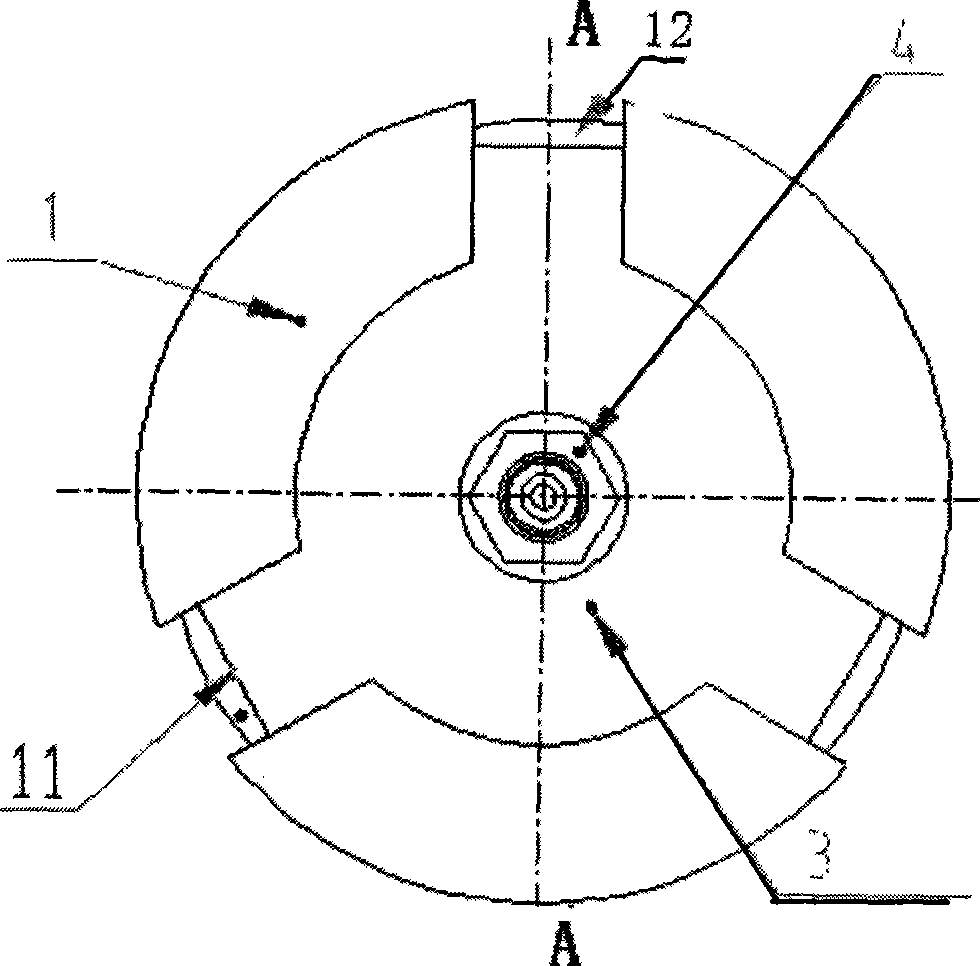
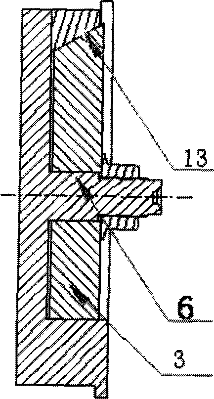
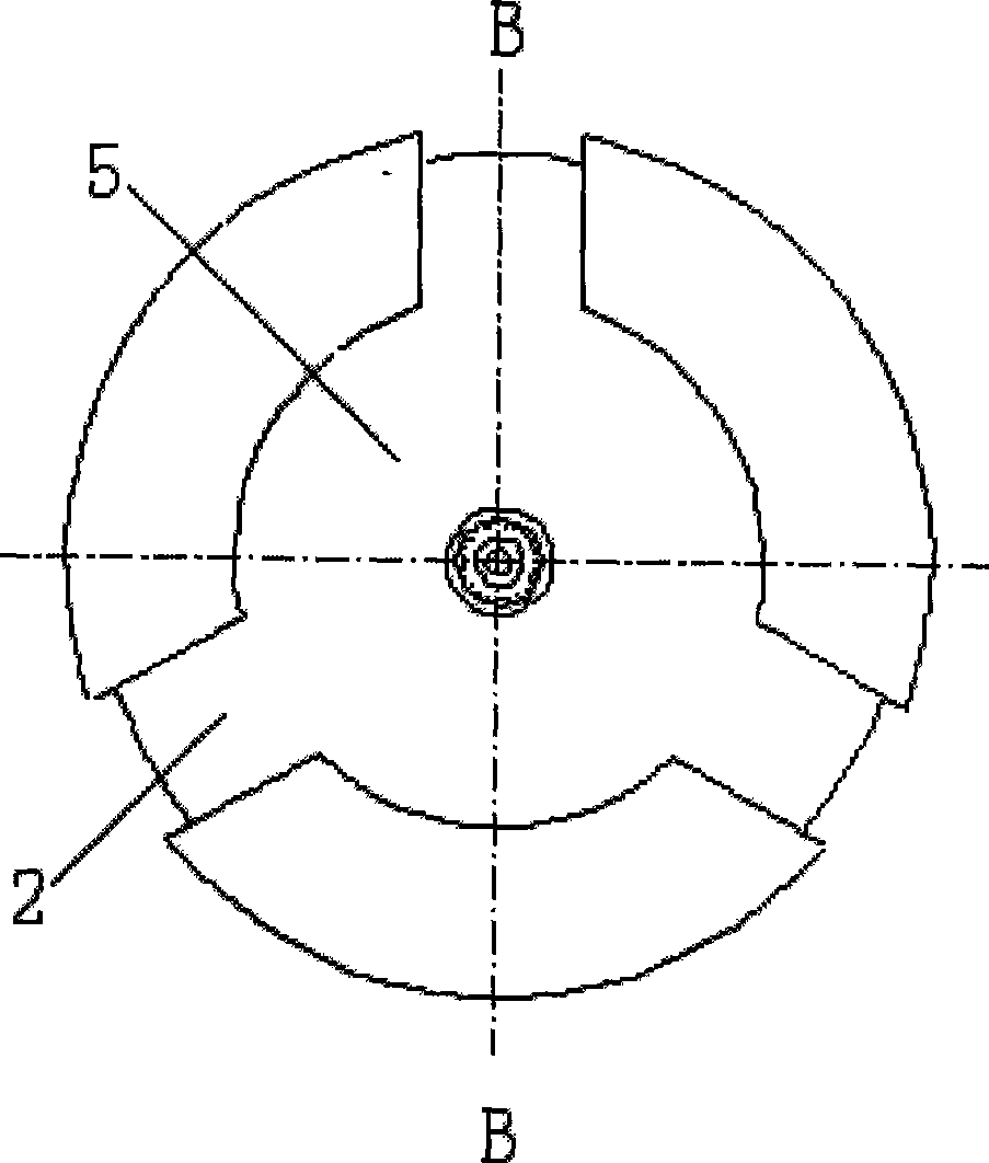
[0017] exist Figure 1 ~ Figure 4 Among them, on the end face of the target ball installation base 1 with positioning post 6, be shaped on image 3 As shown, around the circumference of the central groove 5, it extends radially outward, and its axis of symmetry intersects the chute 2 at the center of the circle. The outer edge of center slide block 3 is shaped on slide block inclined-plane 11. Three chutes are equally distributed along the 120 ° of center groove 5 circumferences. The positioning column 6 is located in the center of the central groove and extends vertically upwards, and protrudes from the end surface. On the positioning column 6, there is a screw type target ball installation head 7. The free end end face of screw type target ball mounting head 7 is shaped on the conical mouth surface sinking hole of laying target ball 9, and a cylindrical magnet 8 that sucks target ball 9 is housed in the hole. The target ball 9 can be a sphere with corner cube mirrors or ...


PUM


Abstract

The invention discloses a target ball mount which is used for mounting target balls of a laser tracking instrument and suitable for large-aperture self-centering, wherein an equant sliding chute (2) which is around the circumference of a central groove (5), intersected with the circle center by being symmetrical with an axial line, and extended outwards in the radial direction is arranged on a target ball mounting base (1); a screw target ball mounting head (7) is arranged on a positioning pin (6), positioned in the center of the central groove, extended upwards vertically, and extended out of the end face; a central slider (3) of which the shape and the dimension are consistent with those of the central groove provided with the equant sliding chute (2) is arranged inside a central sliding chute through a central positioning hole of the central slider (3); a slider bevel (11) is arranged on the central slider (3); and lug bevels (13) are arranged on uniformly distributed movable lugs (12) in equant parts. The invention utilizes the slider bevel to fix the target ball mount on a hole to be measured with large common difference, guarantees superposition of the center of the target ball mount and the center of the hole to be measured, and reduces mounting errors; and the target ball mount is convenient to assemble and disassemble, and suitable for laser tracing measurement of target balls with the aperture between 30 and 80 millimeters and the aperture common difference less than IT12.

Description

technical field [0001] The invention relates to a device for laser tracking and measuring the coordinate position of a target ball, more specifically, the invention relates to a self-centering mounting base for installing the target ball. Background technique [0002] Laser tracking measurement is to use the laser to strike the corner cube and return the light to the original path, and calculate the coordinate value of the target ball position according to the direction of the laser emission and the distance from the laser emitting point to the target ball. Laser tracking measurement is characterized by large measurement range and high measurement accuracy. For example, the measurement radius of the Leica LTD840 laser tracker is 40m, and the measurement accuracy in the full range can reach ±15μm+6μm / m. Since the shape of the target ball is spherical, there is no other surface that can be used for positioning except for the spherical appearance. When using laser tracking mea...

Claims


Application Information

Patent Timeline
Patent Type & Authority Applications(China)
IPC IPC(8): G01B11/00G01S7/481G01S17/42
Inventor 黄跃万世明李江雄柯映林
Owner CHENGDU AIRCRAFT INDUSTRY GROUP
Learn More