
Cleaning method and special cleaner for liquid storage cylinder of hydraulic shock absorber

A technology for hydraulic shock absorbers and liquid storage cylinders, which is applied to cleaning methods and appliances, chemical instruments and methods, and cleaning hollow objects, etc. It can solve the problems of high cleaning costs, large energy consumption, and affecting the viscosity of shock absorbing oil, etc., to achieve Low cleaning cost, high cleaning efficiency and strong carrying capacity

Inactive Publication Date: 2011-08-24
CHENGDU NINGJIANG SHOWA AUTOMOBILE PARTS
View PDF6 Cites 7 Cited by
  • Summary
  • Abstract
  • Description
  • Claims
  • Application Information

AI Technical Summary

Problems solved by technology

At present, the cleaning of the liquid storage cylinder before the final assembly is usually done by brushing or ultrasonic cleaning, but no matter what kind of cleaning is done, it is washed with water. In order to enhance the cleaning effect, 1.5% to 2.5% cleaning agent is usually added to clean water and the aqueous solution is heated. , to improve the surface activity of the liquid storage cylinder and weaken the adsorption force of particles, so the water and electricity consumption is large and the cleaning cost is high. Although the cleaning liquid must be treated and then discharged, it will still have a certain impact on the environment, so there is Pollution
Although there is a drying process after washing, the energy consumption is large, which increases the cleaning cost, and there may be residual water and cleaning agents. Emulsification affects the viscosity of the shock absorber oil and weakens the performance of the shock absorber. When used in a low temperature environment, the residual moisture will also produce ice, which will cause the performance of the shock absorber to fail

Method used


Image

  • Cleaning method and special cleaner for liquid storage cylinder of hydraulic shock absorber
  • Cleaning method and special cleaner for liquid storage cylinder of hydraulic shock absorber
  • Cleaning method and special cleaner for liquid storage cylinder of hydraulic shock absorber

Examples


Embodiment 1

[0044] This embodiment is a fully manual model, which is provided with a dust brushing position, a dust suction position, a compressed gas source, a compressed gas pipeline containing a filter and connected to the compressed gas source, a negative pressure dust suction device, and a negative pressure dust suction device. Negative pressure pipeline connected to the device. Wherein, the negative pressure dust collection device is an industrial vacuum cleaner, and the compressed air source is an air compressor.

[0045] The dust brush position is provided with a brush rod, a brush head, a reciprocating mechanism, and a self-rotating drive mechanism, and the brush head is installed at one end of the brush rod; The relative axial movement is driven by the self-rotation drive mechanism to rotate relative to the axial direction of the brush rod. Specifically, the brush bar is a rack and is fixed on the handle through a dovetail sliding structure. The dovetail sliding mechanism inclu...

Embodiment 2

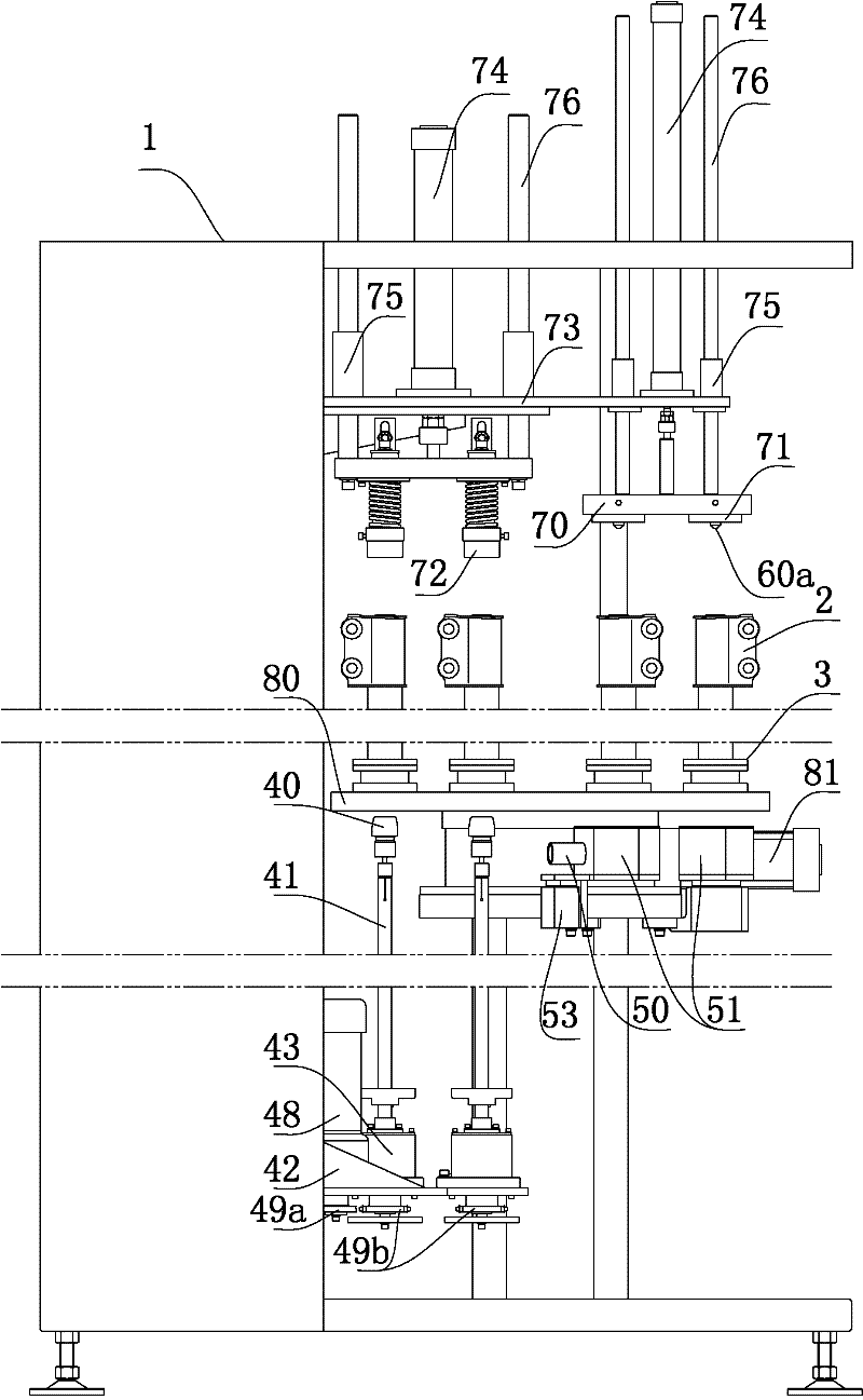
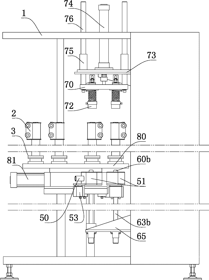
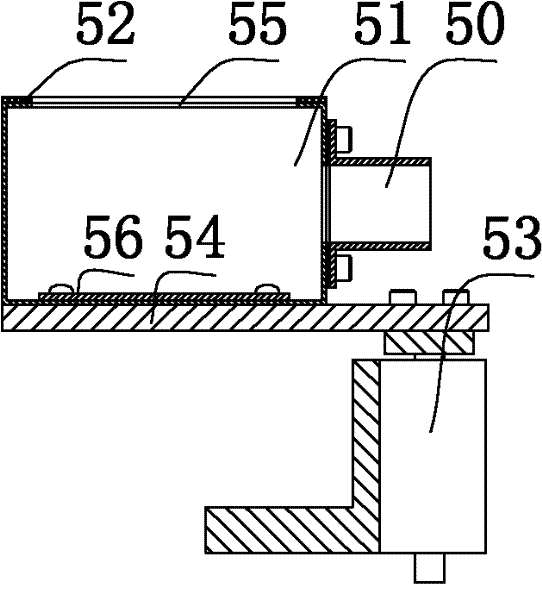
[0051] Such as figure 1 , figure 2 , image 3 , Figure 4 , Figure 5 , Figure 6 , Figure 7 As shown, the cleaning machine of the hydraulic shock absorber liquid storage cylinder in this embodiment is a fully automatic model, and is provided with a dust brushing position, a dust collection position, a frame 1, a step-by-step transmission mechanism installed on the frame 1, a Group mounting base 3, compressed gas source, compressed gas pipeline containing a filter and connected to the compressed gas source, negative pressure dust collection device, and negative pressure pipeline connected to the negative pressure dust collection device. The negative pressure dust collection device is an industrial vacuum cleaner, and the compressed air source is an air compressor. The transmission mechanism is a turntable mechanism comprising a turntable 80, a mounting shaft, a stepping motor 81, and a turntable transmission mechanism. The turntable 80 is mounted on the frame 1 through...


PUM


Abstract

The invention relates to the field of manufacturing of liquid storage cylinders of hydraulic shock absorbers and provides a cleaning method for a liquid storage cylinder of a hydraulic shock absorber. The method comprises the following steps of: dryly brushing the inner cavity of the liquid storage cylinder through relative axial movement and relative rotation of a brush and the liquid storage cylinder; and then aerating the inner cavity to blow the inner cavity and exhausting the inner cavity to suck dust in the inner cavity while the inner cavity of the liquid storage cylinder is sealed. A special cleaner is provided with a dust brushing position, a dust sucking position, a compressed air source, a filter-containing compressed air pipeline, a negative pressure dust sucking device and a negative pressure pipeline, wherein a brush head of the dust brushing position and the liquid storage cylinder do relative axial movement along the axial direction of a brush rod through the driving of a reciprocating mechanism and do relative rotation along the axial direction of the brush rod through the driving of a rotation driving mechanism; and in the dust sucking position, a sealing structure seals the inner cavity of the liquid storage cylinder to form a sealed dust sucking cavity, and the cavity wall of the whole dust sucking cavity is blown and the dust in the dust sucking cavity is sucked through a dust sucking structure and a blowing structure. The cleaning effect is good; clean water, a detergent and drying are not required; the method is environment-friendly, and is low in consumption and low in cost; and no liquid is left. Therefore, the method is suitable for cleaning the liquid storage cylinder before the liquid storage cylinder is assembled.

Description

technical field [0001] The invention relates to the field of manufacturing a shock absorber liquid storage cylinder, in particular to a cleaning method and a special cleaning machine for a hydraulic shock absorber liquid storage cylinder. Background technique [0002] The internal cleanliness of the shock absorber liquid storage tank has a great influence on the performance of the shock absorber, especially the particles attached to the inner cavity wall of the liquid storage tank. The particles will cause seal wear and gap formation during operation, which will affect the two sides of the liquid storage tank. The tightness between the two oil chambers will lead to the failure of the shock absorber function, abnormal noise, etc. Therefore, the liquid storage cylinder needs to be cleaned before final assembly. The cleaning is mainly to remove residual cutting and dust attached during transportation, etc. particulate pollution. At present, the cleaning of the liquid storage c...

Claims


Application Information

Patent Timeline
Patent Type & Authority Applications(China)
IPC IPC(8): B08B9/08B08B9/20
Inventor 李平曾贞陈双
Owner CHENGDU NINGJIANG SHOWA AUTOMOBILE PARTS
Learn More