
On-line measuring device for frictional force generated during polishing of small-sized wafer

A measuring device and friction force technology, which is applied in the direction of grinding/polishing equipment, surface polishing machine tools, semiconductor/solid-state device testing/measurement, etc., can solve the problems of high precision of measuring devices, small friction, covering, etc., and achieve measurement High precision requirements, avoiding measurement errors, and high measurement accuracy

Inactive Publication Date: 2011-08-17
DALIAN UNIV OF TECH
View PDF5 Cites 7 Cited by
  • Summary
  • Abstract
  • Description
  • Claims
  • Application Information

AI Technical Summary

Problems solved by technology

Due to the different friction force and force arm of each wafer, it is difficult to accurately calculate the friction force of a single wafer through the combined force of all test pieces
Even if there is an eccentricity between the center of rotation of the polishing head and the center of rotation of the polishing disc, the friction force on a single wafer cannot be calculated using this method
[0004] In a word, in the polishing where the polishing head moves and the wafer size is small, the friction force is small, and the precision of the measuring device required is high. Using the current existing method will inevitably introduce measurement errors, and usually several wafers are attached to the bottom of the polishing head. At present, Existing measurement methods can only measure the resultant force of the friction force of several wafers. The friction force direction of different wafers is different. The resultant force will cover up the information of the friction force on a single wafer, and cannot accurately reflect the friction force of a single wafer in each rotation cycle. and changes

Method used


Image

  • On-line measuring device for frictional force generated during polishing of small-sized wafer
  • On-line measuring device for frictional force generated during polishing of small-sized wafer
  • On-line measuring device for frictional force generated during polishing of small-sized wafer

Examples


Embodiment

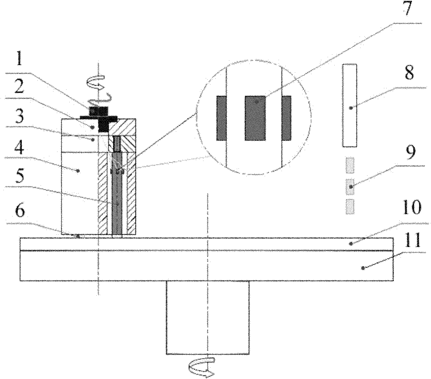
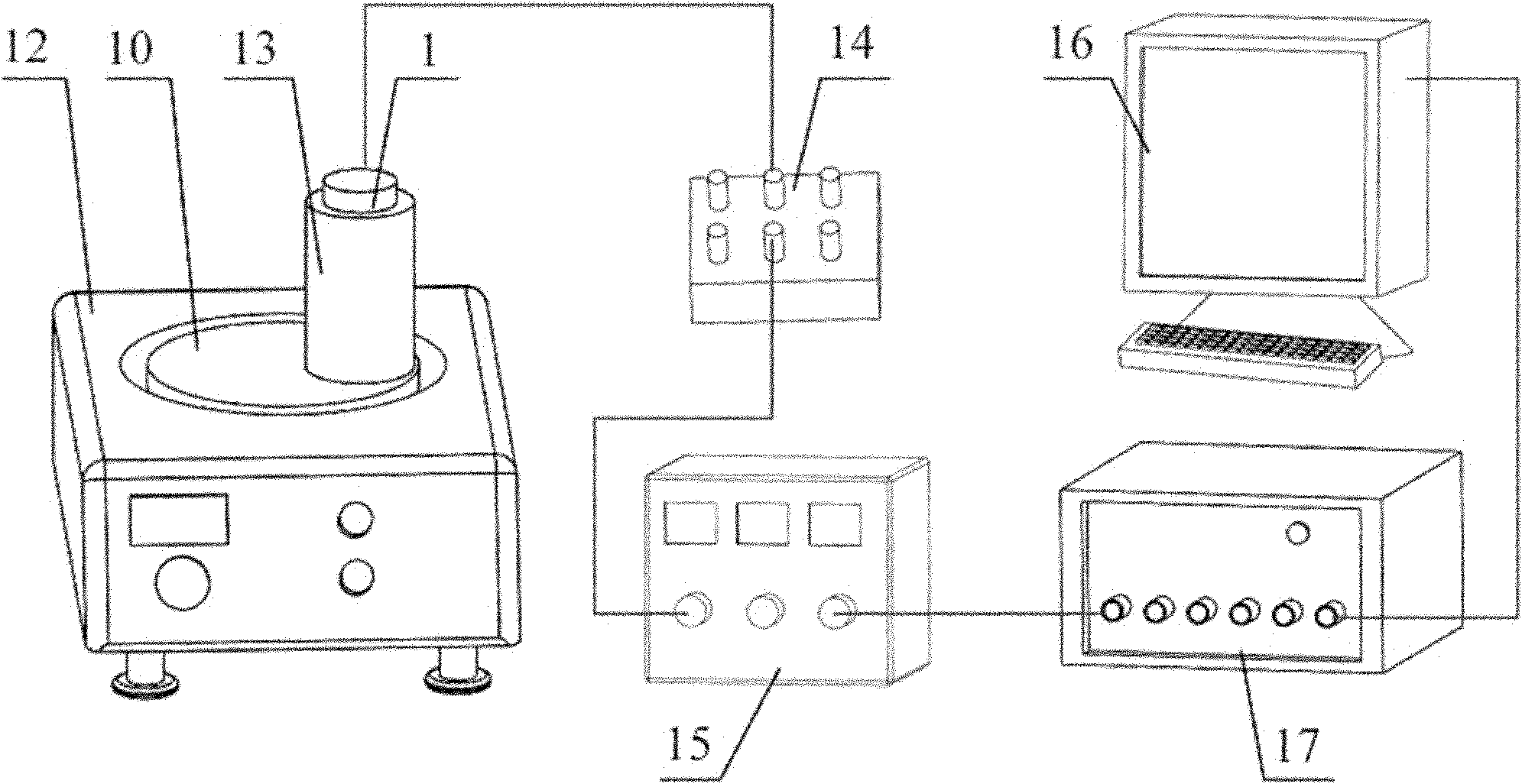
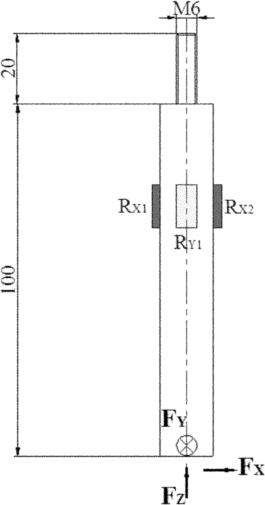
[0018] as attached figure 1 As shown, the structure of the polishing head mainly includes a slip ring 1 , a counterweight A2 , a counterweight B3 , a counterweight C4 , an elastic element 5 , a chip 6 , and a strain gauge 7 . The counterweight C4 has a diameter of 100 mm and a length of 100 mm. A light hole with a diameter of 20mm is processed on it. Process the M6 ​​threaded hole on the counterweight B3, and the threaded hole is coaxial with the light hole of the counterweight C4. Different polishing pressures can be realized by adjusting the number and height of the counterweight B3. The elastic element 5 is made of aluminum alloy and has a length of 120 mm. The diameter of the lower cylindrical part is 15mm, and the length is 100mm, and the upper end is an M6 thread, and the length is 20mm. Put the elastic element 5 into the hole of the counterweight C4, and fix it on the counterweight B3 through the thread of M6. During the assembly process, ensure that the cylindrica...


PUM


Abstract

The invention relates to an on-line measuring device for frictional force generated during the polishing of a small-sized wafer, comprising a polishing head, a resistance strain gauge, a data acquisition instrument, a conducting wire and a computer, wherein the polishing head consists of a balancing weight, an elastic element, a resistance strain gage and a collecting ring. During polishing, the frictional force applied to the wafer causes the elastic element in the polishing head to generate elastic deformation, the resistance strain gage attached to the surface of the elastic element converts the elastic strain of the elastic element into an electrical signal which is transferred to the resistance strain gauge through the collecting ring, and finally, the data acquisition instrument inputs the electrical signal into the computer. The device has the advantages of carrying out on-line measurement on the frictional force generated during the polishing of the small-sized wafer, without changing the polishing state, thus being applicable to the polishing mode that the polishing head rotates along with a polishing disk. The method directly measures the frictional force applied to a single wafer, and avoids measurement error generated due to the measurement on resultant frictional force of a plurality of wafers as well as mechanical analysis and calculation errors needed by indirect measurement. The device achieves high measurement accuracy, and is suitable for occasions where the frictional force of the small-sized wafer is low and the requirement on measurement accuracy is high.

Description

technical field [0001] The invention belongs to the technical field of crystal material polishing, and relates to an online measuring device for small-sized wafer polishing friction force. Background technique [0002] With the development of microelectronics, optoelectronics, superconductors, optical lenses and other industries, various crystal materials such as diamond, single crystal silicon, sapphire and magnesium oxide are increasingly widely used. The products in these industries have extremely strict requirements on the quality of the wafer surface, and the surface must be polished precisely or ultra-precisely. At present, the more efficient polishing methods are mainly contact polishing such as mechanical polishing and chemical mechanical polishing. The mechanical action on the wafer directly affects the polishing efficiency and surface quality. Accurate quantification of mechanical action is important for studying the polishing mechanism and guiding the polishing pr...

Claims


Application Information

Patent Timeline
Patent Type & Authority Applications(China)
IPC IPC(8): H01L21/66H01L21/304B24B29/02
Inventor 金洙吉苑泽伟王坤康仁科
Owner DALIAN UNIV OF TECH
Learn More