


Quick Research
Generate reliable direction feasibility study reports for your R&D in just a few steps.

Technical Q&A
Discover and master advanced knowledge NOW. Basics, ideas, possibilities, all at once.

Find Solutions
As an expert in R&D theories, this can generate solutions to your technical problems instantly.

Evaluate Feasibility
Analyze your overall solution with one click, know your potential R&D risks in advance.

Monitor Landscape
Get weekly tech updates, stay abreast of the latest tech innovations and key insights.
Laser scribing method and device
A laser scribing and laser technology, applied in laser welding equipment, welding equipment, metal processing equipment, etc., can solve problems such as unfavorable cost and complicated equipment
- Summary
- Abstract
- Description
- Claims
- Application Information
AI Technical Summary
Problems solved by technology
Method used
Image


Examples
Embodiment
[0075] In the case of forming a scribed groove on a workpiece using a laser scribing device that splits the laser light emitted from a laser source to form multiple beam spots, the relationship between the out-of-focus position and the depth of the groove was studied. .
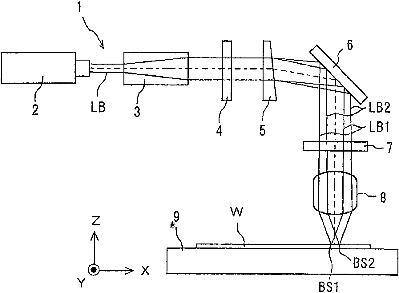
[0076] The laser scribing device is used figure 2 In the shown laser scribing device, the components of the 1 / 4 wavelength plate are omitted.
[0077] As a laser source, Nd:YAG laser (wavelength 1064nm, output 10W) was used. The output characteristics of the laser light were set as shown in Table 1.
[0078] For the birefringent element, a crystal plate with a wedge angle of 2° is used.
[0079] As the condenser lens, a lens with a focal length f of 50 mm is used.
[0080] The workpiece is made of alumina ceramic with a thickness of 0.28mm.
[0081] The scribing speed (moving speed of the beam spot) SP was set at 50 mm / sec.
[0082] The depth of the scribe groove was measured at points (10 μm pitch) ...
PUM
| Property | Measurement | Unit |
|---|---|---|
| Thickness | aaaaa | aaaaa |
Abstract
Description
Claims
Application Information
 - R&D Engineer
- R&D Manager
- IP Professional
- Industry Leading Data Capabilities
- Powerful AI technology
- Patent DNA Extraction
Browse by: Latest US Patents, China's latest patents, Technical Efficacy Thesaurus, Application Domain, Technology Topic, Popular Technical Reports.
© 2024 PatSnap. All rights reserved.Legal|Privacy policy|Modern Slavery Act Transparency Statement|Sitemap|About US| Contact US: help@patsnap.com