
Electrostatic capacitive type touch panel and display device equipped with a touch detection function

A touch detection and touch panel technology, applied in the field of capacitive touch panels and display devices with electrostatic capacitance type touch detection function, can solve the problems of touch panel failure, indistinguishable interference noise, etc., achieve reliable touch detection, shorten time, The effect of simplifying the circuit structure

Inactive Publication Date: 2011-07-27
JAPAN DISPLAY INC
View PDF4 Cites 42 Cited by
  • Summary
  • Abstract
  • Description
  • Claims
  • Application Information

AI Technical Summary

Problems solved by technology

However, in the capacitive touch panel, the human body acts as an antenna for noise (hereinafter referred to as disturbance noise) due to inverter fluorescent lamps, AM waves, or AC power, etc., and there is a possibility that malfunctions may be caused by noise propagating to the touch panel
[0003] This malfunction is caused by a signal related to the presence or absence of a touch (hereinafter, referred to as a touch signal) generated by a user's finger or the like touching or approaching the touch panel, and the disturbance noise is indistinguishable

Method used


Image

  • Electrostatic capacitive type touch panel and display device equipped with a touch detection function
  • Electrostatic capacitive type touch panel and display device equipped with a touch detection function
  • Electrostatic capacitive type touch panel and display device equipped with a touch detection function

Examples


no. 2 example

[0050] 4. The third embodiment

[0051] 5. Application example

[0052]

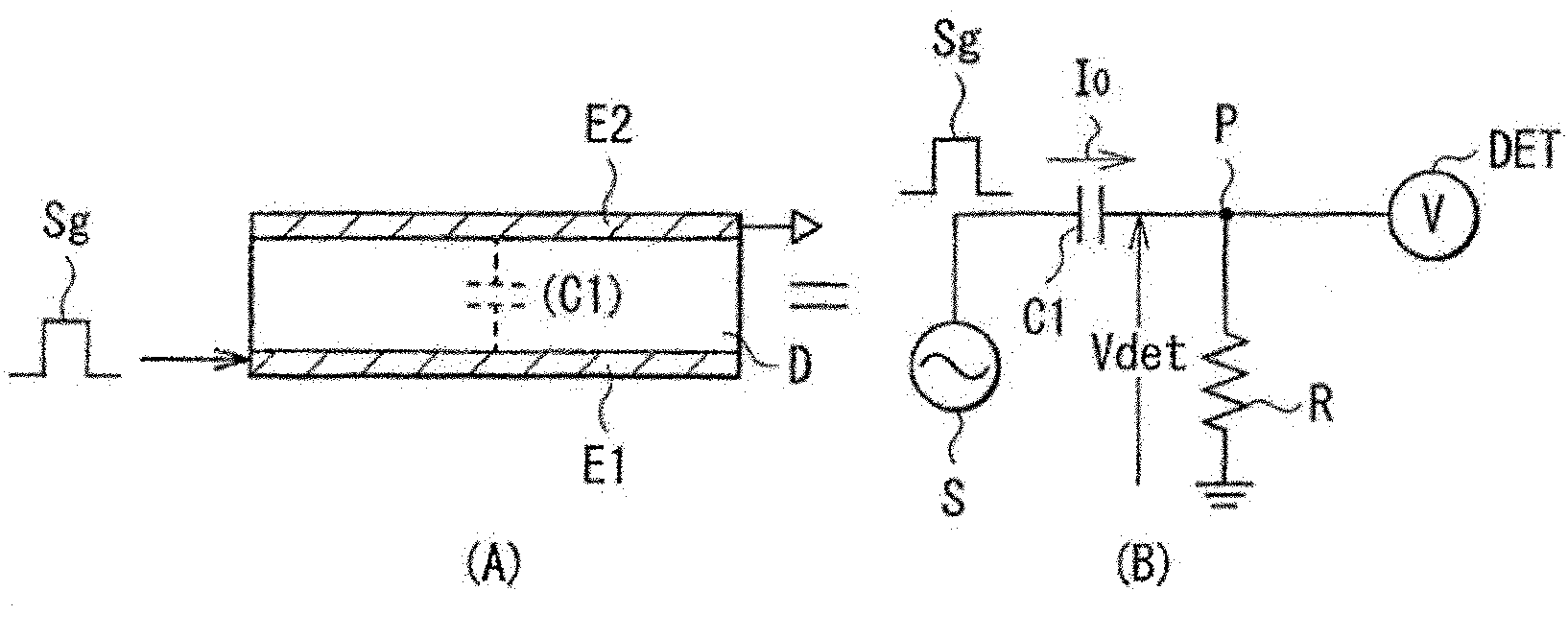
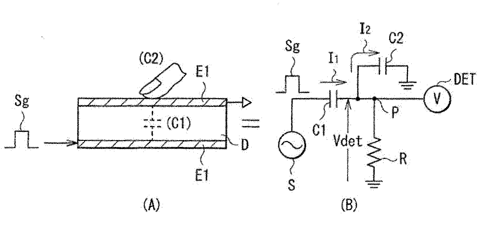
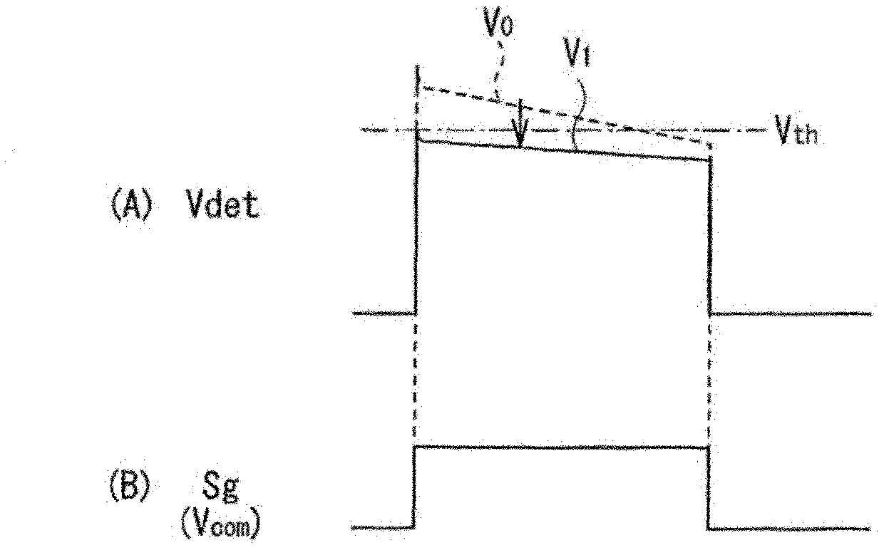
[0053] First, refer to Figure 1 to Figure 3 The basic principle of the touch detection method in the capacitive touch panel of the present invention is described. For example, if figure 1 As shown in (A), in this touch detection method, a capacitive element is constructed by using a pair of electrodes (drive electrode E1 and detection electrode E2 ) arranged to face each other with a dielectric body D in between. The structure is represented as figure 1 Equivalent circuit shown in (B). The capacitive element C1 is composed of a driving electrode E1 , a detecting electrode E2 and a dielectric D. In the capacitive element C1, one end is connected to an AC signal source (drive signal source) S, and the other end P is grounded through a resistor R and connected to a voltage detector (detection circuit) DET. When an AC rectangular wave Sg ( image 3 (B)), in the detection electrode E2 (the other end...

no. 3 example

[0179] Next, a display device having an electrostatic capacitance type touch detection function according to a third embodiment of the present invention will be described. In addition, the same reference numerals are used for substantially the same components as those of the capacitive touch panels according to the first and second embodiments, and descriptions will be omitted.


PUM


Abstract

Disclosed is an electrostatic capacitive type touch panel which has a simple construction and makes it possible to reduce noise due to external interference and to shorten the touch detection time. The touch panel is provided with: a plurality of drive electrodes to which drive signals for touch detection are applied; a plurality of touch detection electrodes that output detection signals synchronised with the drive signals, and are arranged intersecting the drive electrodes; a first series of sampling circuits (A / D conversion circuits (72, 73)) that extract a first series of sampling signals including a signal component of a first level and a noise component from the detection signals; second sampling circuits (A / D conversion circuits (75, 76)) that extract a second series of sampling signalsincluding a signal component of a second leveldifferent from the first leveland a noise component from the detection signals; filter circuits (digital LPFs (81, 82)) that perform high-band cut-off processing in respect of the first and second series of sampling signals; and a calculation circuit (subtraction circuit (90)) that finds a touch detection signal from the outputs of the filter circuits.

Description

technical field [0001] The present invention relates to a touch panel capable of inputting information through contact or proximity of a user's finger, etc. function of the display device. Background technique [0002] In recent years, information input has been enabled by mounting a contact detection device (so-called touch panel) on a display device such as a liquid crystal display device, and displaying various button images on the display device instead of typical mechanical buttons. The display device has attracted attention. There are several methods of touch panels, such as optical methods and resistive methods, and capacitive touch panels capable of realizing low power consumption while having a relatively simple structure are desired particularly in portable terminals and the like. However, in the capacitive touch panel, the human body acts as an antenna for noise (hereinafter referred to as disturbance noise) due to inverter fluorescent lamps, AM waves, or AC pow...

Claims


Application Information

Patent Timeline
Patent Type & Authority Applications(China)
IPC IPC(8): G06F3/044G06F3/041
CPCG06F3/044G06F3/0418G06F3/0412G06F3/04182G06F3/0445G06F3/0446
Inventor 木田芳利石崎刚司野口幸治竹内刚也原田勉中西贵之
Owner JAPAN DISPLAY INC
Learn More