
Pellicle frame, pellicle and method for using pellicle frame

A surface film and component technology, which is applied in the photoengraving process of the pattern surface, the original for photomechanical processing, optics, etc., can solve the problems of increased mask weight, deflection, etc., and achieve remarkable results.

Active Publication Date: 2011-07-20
ASAHI KASEI KK
View PDF5 Cites 4 Cited by
  • Summary
  • Abstract
  • Description
  • Claims
  • Application Information

AI Technical Summary

Problems solved by technology

[0010] This problem is that the photomask and the reticle (hereinafter referred to simply as the mask) themselves are also required to be increased in size due to the further increase in size in recent years, and thus a problem has arisen due to the increase in the size of the mask in the past. The further enlargement of itself causes the problem of deflection of the mask due to the increase in its own weight
[0013] In this way, the ultra-large size of the mask has created new problems for the super-large surface film member applied to this type of mask.

Method used


Image

  • Pellicle frame, pellicle and method for using pellicle frame
  • Pellicle frame, pellicle and method for using pellicle frame
  • Pellicle frame, pellicle and method for using pellicle frame

Examples


Embodiment 1~99、 comparative example 1~71

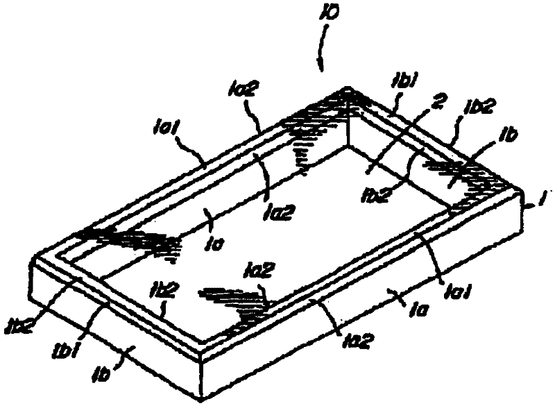
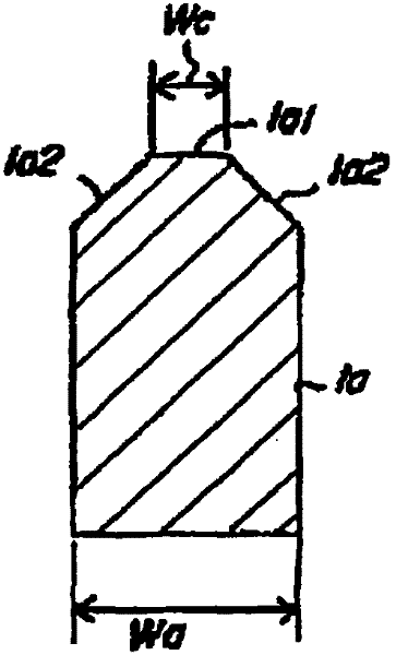
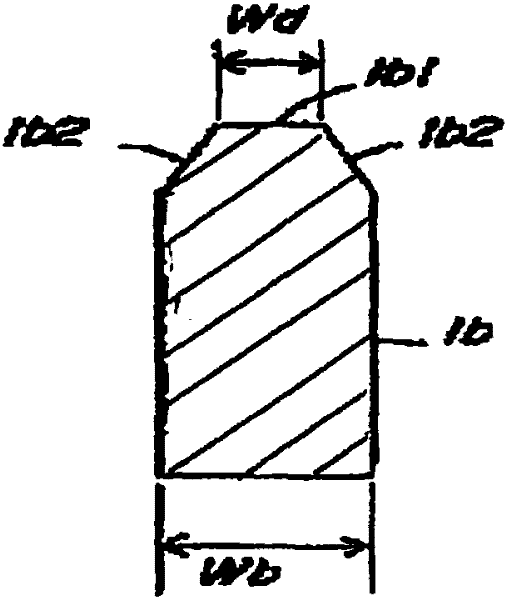
[0124] The length (La) of the long side 1a, the length (Lb) of the short side 1b, the inner area (effective area) of the frame 1, and the thickness of the frame 1 for super-large pellicle members are shown in Tables 1 to 9. . In addition, the width (Wa) of the long side 1a and the width (Wb) of the short side 1b of the surface film member frame are as shown in Table 1-Table 9.

[0125] In addition, aluminum alloy is used for the material of the frame of the surface film member, and the cross-sectional shape of the frame is rectangular. In addition, the surface film member frame used is a frame body without microcracks that has been subjected to black aluminum passivation treatment.

[0126] The performance of the actual surface film member was evaluated using the frame as described above.

[0127] The details are as follows.

[0128] As the surface film, a polymer solution of cellulose ester was coated on low-alkali glass, and the main film was formed by spin coating.

[0...

Embodiment 100~197、 comparative example 72~141

[0141] The length (La) of the long side 1a, the length (Lb) of the short side 1b, and the inner area (effective area) of the frame of the super-large pellicle member frame 1 used in Examples and Comparative Examples are shown in Tables 10 to 16. shown. Tables 10 to 16 also show the width (Wa) of the long side 1a, the width (Wb) of the short side 1b of the pellicle member frame, and the thickness of the pellicle member frame.

[0142] In addition, aluminum alloy is used for the material of the frame of the surface film member, and the cross-sectional shape of the frame is rectangular. In addition, the frame of the surface film member used was a frame without microcracks to which black passivated aluminum was applied.

[0143] The performance was actually evaluated using a frame for a surface film member having the above-mentioned specifications.

[0144] As the surface film, a polymer solution of cellulose ester was coated on low-alkali glass, and the main film was formed by ...


PUM

PropertyMeasurementUnit
lengthaaaaaaaaaa
thicknessaaaaaaaaaa
lengthaaaaaaaaaa

Abstract

The present invention provides a pellicle frame, a pellicle and a method for using the pellicle frame, wherein the pellicle frame is not distorted when a pellicle film is stretched and pasted, and the pellicle frame itself follows up flexure caused by the weight of a mask even after a pellicle is pasted to the mask. A rectangular pellicle frame has a distortion factor alpha of 0.06% or less, the followability beta of each side of the pellicle frame expressed by the general expression (1) is 3 mm or more, the followability beta of the long side of the pellicle frame is 32 mm or less, the long side of the pellicle frame has a length of 1400-2100 mm, and the area on the inside of the pellicle frame is 15000 cm2 or more, wherein beta =(1 / flexure of pellicle)*thickness*width (1).

Description

technical field [0001] The present invention relates to a frame as a constituent member of a pellicle, particularly a pellicle frame as a constituent member of a super-large pellicle with a long side length greater than 1400 mm, and a watch using the pellicle frame. A method of using a film member and a frame of a film member for preventing the photolithography process used in the manufacture of a thin film transistor (TFT) constituting an LSI, a liquid crystal display (LCD), a color filter (CF), etc. Foreign matter adheres to the photomask and reticle. Background technique [0002] The present invention relates to a technology related to a frame and a surface member as constituent members of the surface member, and the surface member will be described first. [0003] Conventionally, when manufacturing semiconductor circuit patterns and the like, a dustproof member generally called a pellicle is used to prevent foreign matter from adhering to a photomask or a reticle. The ...

Claims


Application Information

Patent Timeline
Patent Type & Authority Applications(China)
IPC IPC(8): G03F1/14G03F1/64
CPCG03F1/64
Inventor 北岛慎太郎栗山芳真
Owner ASAHI KASEI KK
Learn More