Cooking device

A cooker and heater technology, applied in the direction of heating methods, electric heating fuel, lighting and heating equipment, etc., can solve the problem of low heating efficiency and achieve the effect of improving heating efficiency and reducing outflow

Inactive Publication Date: 2011-07-20
SHARP KK
View PDF4 Cites 7 Cited by
  • Summary
  • Abstract
  • Description
  • Claims
  • Application Information

AI Technical Summary

Problems solved by technology

Therefore, the steam generated by the steam generator cannot be used sufficiently for cooking, and there is a problem that the heating efficiency becomes low.

Method used


Image

  • Cooking device
  • Cooking device
  • Cooking device

Examples


Embodiment Construction

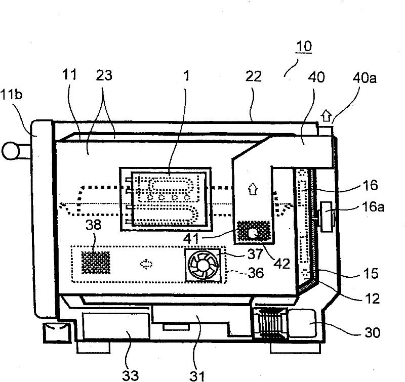
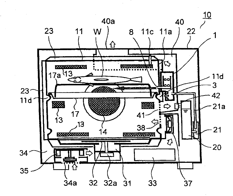
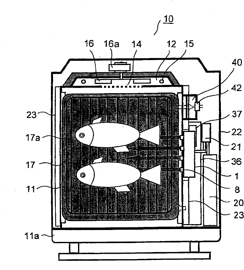
[0021] Embodiments of the present invention will be described below with reference to the drawings. figure 1 , figure 2 , image 3 It is a right side view, a front view, and a top cross-sectional view which show the inside of the heating cooker which concerns on one Embodiment. The heating cooker 10 has a substantially rectangular parallelepiped heating chamber 11 in which cooking items are accommodated in a main body casing 22 . The side wall and ceiling wall of the heating chamber 11 are covered with the heat insulation board 23, and the front surface is opened and closed by the door 11b.

[0022] The temperature sensor 11c which detects the indoor temperature of the heating chamber 11 is provided in the ceiling surface of the heating chamber 11. As shown in FIG. Based on the detected temperature of the temperature detector 11c, the convection heater 15 described later is controlled. An installation portion 11 d is protrudingly provided on a side wall in the heating ch...


PUM


Abstract

A cooking device comprises: a heating chamber (11) equipped with a placement section (11d), the placement section (11d) being adapted such that a tray (17) is placed thereon, the tray (17) having a placement net (17a) for placing thereon an object to be cooked; a vapor generating device (1) for generating vapor and supplying the vapor between the placement net (17a) and the tray (17); a circulation duct (12) having a circulation fan (16) and circulating gas in the heating chamber (11); a convection heater (15) provided in the circulation duct (12); a gas supply opening (38) provided below the tray (17); a gas discharge opening (41) provided below the tray (17); and a magnetron (33) for supplying a microwave to the heating chamber (11). The cooking device is provided with a range mode for performing cooking by a microwave, a grill mode for performing cooking by superheated vapor by driving the circulation fan (16) and the convection heater (15), and a steaming mode for performing cooking by saturated vapor with the circulation fan (16) and the convection heater (15) stopped.

Description

technical field [0001] The present invention relates to a heating cooker for cooking by supplying microwaves to a heating chamber. Background technique [0002] Patent Document 1 discloses a conventional heating cooker that supplies microwaves and cooks. This heating cooker has a heating chamber in which cooking food is stored by opening and closing a door at the front. A magnetron for supplying microwaves to the heating chamber is arranged on one side of the heating chamber, and a blower fan is arranged behind the magnetron. [0003] One side wall of the heating chamber is opened with a supply port for supplying outside air into the heating chamber through the blower fan. An exhaust port for exhausting the gas in the heating chamber is opened on the upper part of the other side wall of the heating chamber. The exhaust port is exposed to the atmosphere through a passage, and a humidity sensor is arranged in the passage. [0004] When cooking starts, the blower fan and th...

Claims


Application Information

Patent Timeline
IPC IPC(8): F24C7/02F24C1/00
CPCH05B6/6479H05B6/6408F24C15/327
Inventor 上田真也下田英雄内海崇
Owner SHARP KK
Why Eureka
Try Eureka