Eureka AIR delivers breakthrough ideas for toughest innovation challenges, trusted by R&D personnel around the world.

Split charging line for engine

A technology of sub-assembly line and engine, applied in conveyors, mechanical conveyors, transportation and packaging, etc., can solve the problems of large area, inconvenient material transportation, and large area of ​​conveyor lines.

Active Publication Date: 2011-07-20
MIRACLE AUTOMATION ENG CO LTD
View PDF7 Cites 4 Cited by
  • Summary
  • Abstract
  • Description
  • Claims
  • Application Information

AI Technical Summary

Problems solved by technology

In practical applications, there is often a phenomenon that the engine sub-assembly conveyor line occupies too much area in a compact workshop
Many existing sub-packaging lines adopt the form of ground push chains, which occupy a large area, have low space utilization, and are inconvenient for material transportation

Method used


Image

  • Split charging line for engine
  • Split charging line for engine
  • Split charging line for engine

Examples


Embodiment Construction

[0015] The present invention will be further described below in conjunction with specific drawings and embodiments.

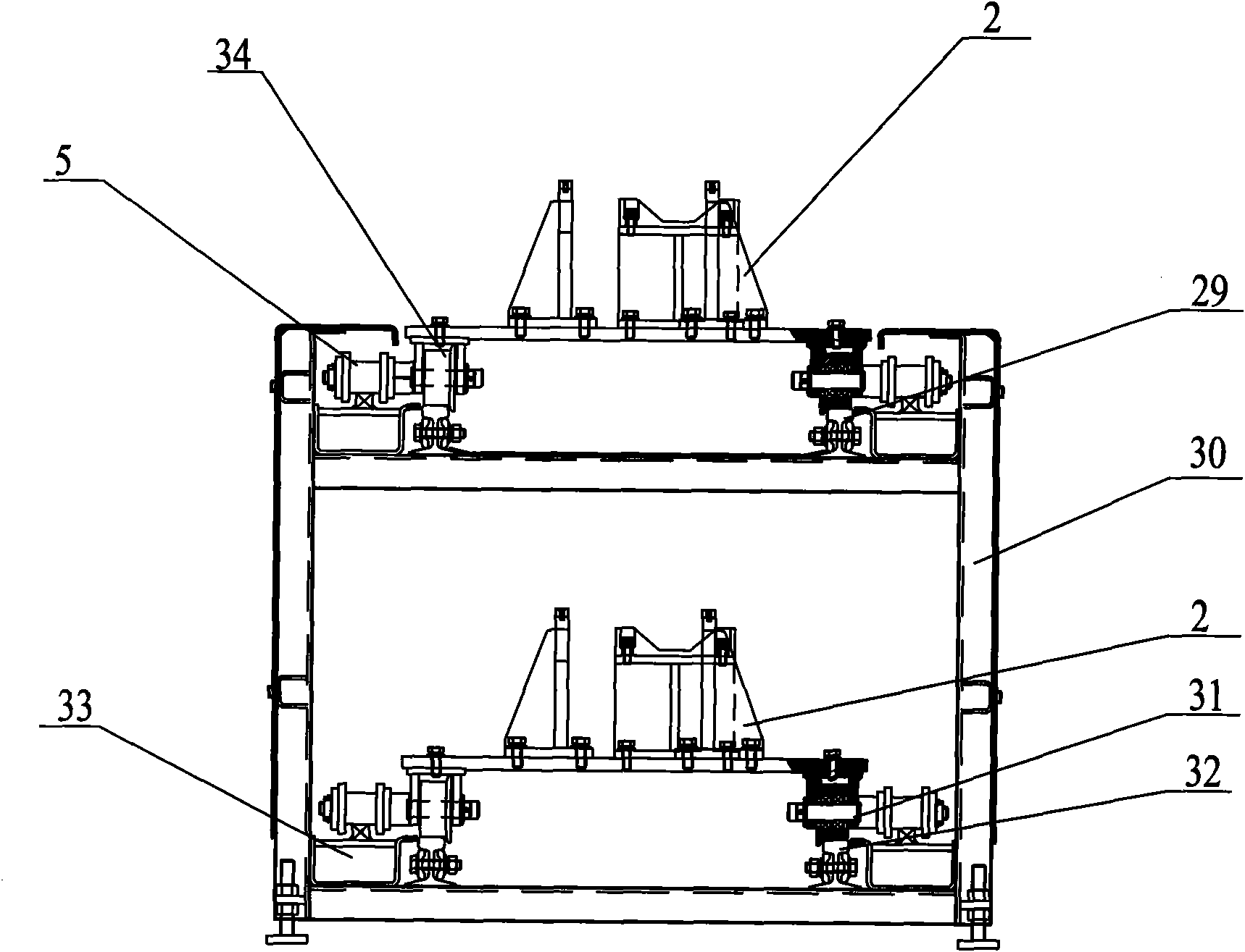
[0016] Such as Figure 1 ~ Figure 6 Shown: the present invention includes a chain drive device 1, an engine tray 2, a subassembly line body 3, a chain tensioning device 4, a first drive chain 5, a drive motor 6, a drive mounting frame 7, an eighth drive wheel 8, and a One tension wheel 9, tension mounting frame body 10, first tension shaft 11, tension adjustment bolt 12, second tension wheel 13, second tension shaft 14, second drive chain 15, fifth drive wheel 16. Drive support shaft 17, second drive shaft 18, sixth drive wheel 19, fourth drive chain 20, third drive wheel 21, first drive shaft 22, first drive wheel 23, end cover 24, third drive Chain 25, second drive wheel 26, fifth drive chain 27, seventh drive wheel 28, upper tray rail 29, sub-assembly line frame 30, running wheel mounting shaft 31, lower tray rail 32, driving rail 33, pallet walking The wheel...


PUM


Abstract

The invention relates to a split charging line for an engine. The split charging line comprises a split charging line frame body; the upper part of the split charging line frame body is provided with an upper tray track; the lower part of the split charging line frame body is provided with a lower tray track; the upper tray track and the lower tray track are provided with an engine tray respectively; the bottom of each engine tray is provided with a tray travelling wheel; a travelling track on one side of the split charging line frame body is provided with a driving chain, and the other side of the split charging line frame body is provided with a second driving chain; a driving connection shaft which is vertically distributed is arranged on the first driving chain and the second driving chain respectively; the corresponding driving connection shafts of the first driving chain and the second driving chain are fixedly connected with the tray travelling wheels at the bottom of the engine tray which are distributed in an opposite angel shape respectively; and one end of a split charging line body is provided with a chain driving device for driving the first driving chain and the second driving chain to rotate. The split charging line has a compact structure, can convey an object conveniently and stably, reduce conveying cost, improve space utilization rate, and is safe and reliable.

Description

Technical field [0001] The invention relates to a subassembly line, in particular to an engine subassembly line, in particular to a loading and conveying line body used in engine subassembly, belonging to the technical field of conveying devices. Background technique [0002] With the development of industrial production, the requirements for conveying equipment are getting higher and higher. Due to various interfaces and process arrangements, the requirements for the layout of the conveyor line in many conveying equipment are getting higher and higher. In practical applications, there is often a phenomenon that the engine sub-assembly conveyor line in a compact workshop takes up too much area. Many existing sub-assembly lines adopt the ground push chain form, which covers a large area, has low space utilization, and is inconvenient for the transportation of materials. Summary of the invention [0003] The purpose of the present invention is to overcome the shortcomings in the p...

Claims


Application Information

Patent Timeline
Patent Type & Authority Applications(China)
IPC IPC(8): B65G37/00B65G35/00
Inventor 戴卫刚白小东唐均
Owner MIRACLE AUTOMATION ENG CO LTD
Why Eureka
Eureka Blog
Learn More