
Soldering and mounting method of electric connector

An electrical connector and installation method technology, applied in the direction of connection, circuit/collector parts, circuits, etc., can solve problems such as short circuit easily, and achieve the effect of improving product qualification rate, reducing production cost, and improving welding and installation efficiency

Inactive Publication Date: 2011-07-13
SUYING ELECTRCNICS (DONG GUAN) CO LTD
View PDF7 Cites 3 Cited by
  • Summary
  • Abstract
  • Description
  • Claims
  • Application Information

AI Technical Summary

Problems solved by technology

[0004] In view of this, the present invention aims at the deficiencies in the prior art, and its main purpose is to provide a method for welding and installing electrical connectors, which can effectively solve the problem that short circuits are prone to occur after conducting terminals and external circuit boards are welded and installed

Method used


Image

  • Soldering and mounting method of electric connector
  • Soldering and mounting method of electric connector
  • Soldering and mounting method of electric connector

Examples


Embodiment Construction

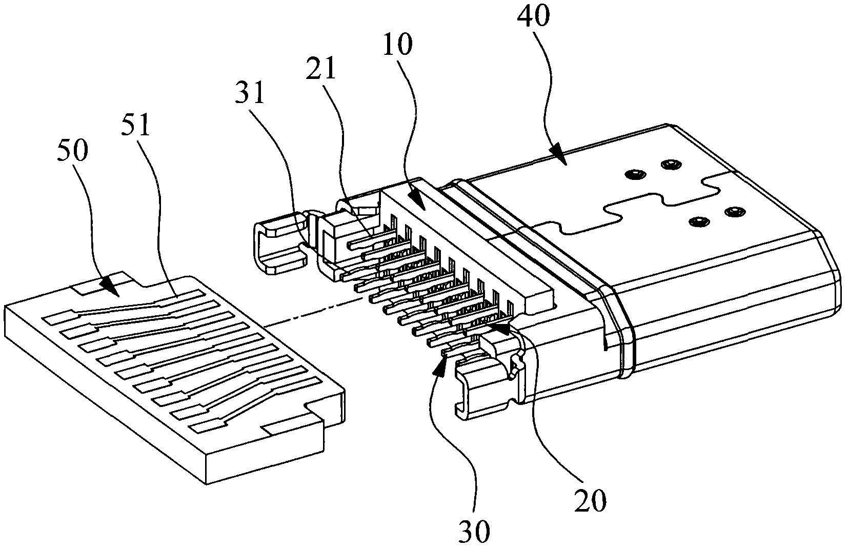
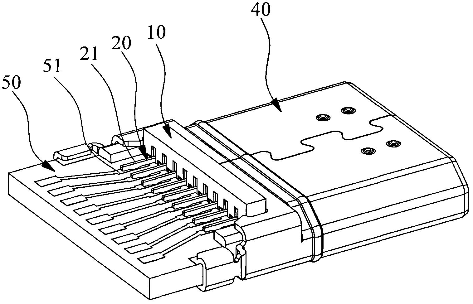
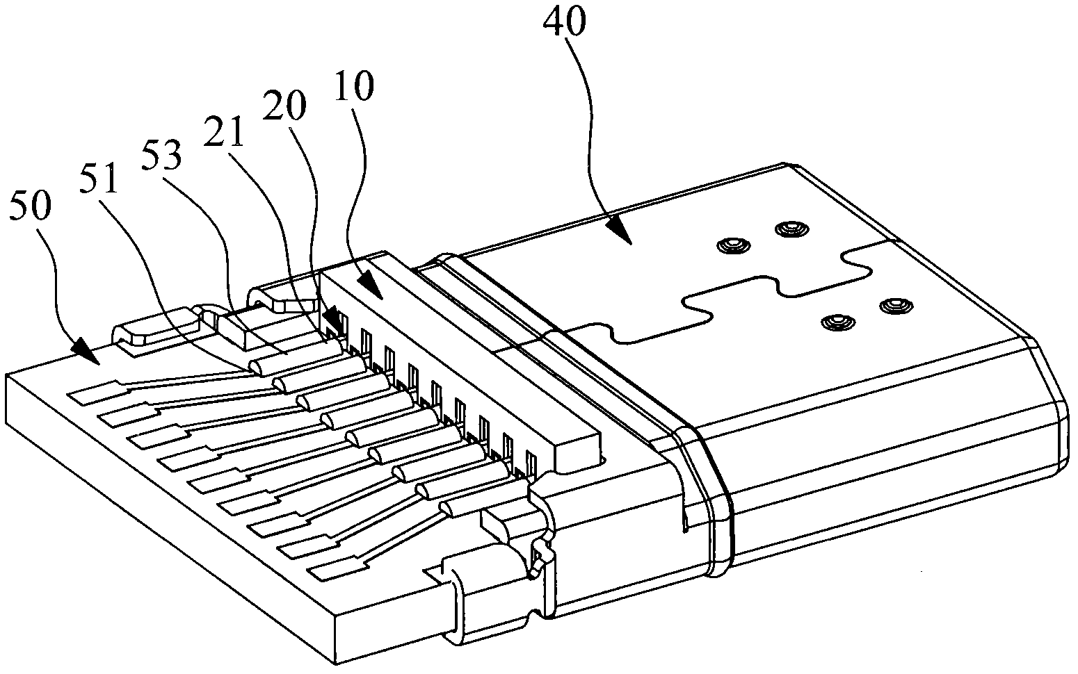
[0032] Please refer to Figure 1 to Figure 6 As shown, it shows the specific structure of the preferred embodiment of the present invention, including an insulating housing 10 , a first conductive terminal 20 , a second conductive terminal 30 , a metal shell 40 and a PCB board 50 .

[0033] Wherein, the first conductive terminal 20 and the second conductive terminal 30 are both disposed on the insulating body 10, and the welding portion 21 of the first conductive terminal 20 and the welding portion 31 of the second conductive terminal 30 both extend out of the insulating body 10, The PIN distance between the first conductive terminal 20 and the second conductive terminal 30 is less than 1.5 mm. The metal shell 40 covers the insulating body 10 , and the metal shell 40 is used to prevent electromagnetic interference.

[0034] The upper surface of the PCB board 50 is provided with a tin-eating area 51, and the lower surface of the PCB board is provided with a tin-eating area 52....


PUM


Abstract

The invention discloses a soldering and mounting method of an electric connector, and the method comprises the following steps: (1) assembling an insulating body, conductive terminals and a metal housing into the electric connector; (2) butting the electric connector with a PCB (printed circuit board), and enabling the soldering parts of the conductive terminals to prop against the corresponding tin soldering region of the PCB, thus forming a semi-finished product; (3) soaking the board end of the semi-finished PCB product into a liquid soldering flux; (4) taking out, then placing the board end of the PCB into a tin furnace, and enabling the part which needs to perform tin soldering to be completely soaked in the tin furnace, wherein the temperature of the tin furnace is 270 DEG C-290 DEG C; and (5) taking the semi-finished product out of the tin furnace, and further cleaning the board end of the PCB with alcohol. Therefore, the soldering parts and the tin soldering region are soldered together by heating through the tin furnace, the phenomenon of easy emergence of soldering short-circuit due to manual soldering can be avoided, the qualification rate of products can be improved, the method is applicable to soldering the electric connectors with small PIN distance, the operation is further simple and high-efficient, and the method is conductive to reducing the production cost of an enterprise.

Description

technical field [0001] The invention relates to the technology in the field of electrical connectors, in particular to a soldering installation method applied to electrical connectors with small PIN pitches. Background technique [0002] Electrical connectors used in computers and various digital products mainly include an insulating body, a conductive terminal and a metal shell. The conductive terminal is arranged on the insulating body. Overlay the insulation body. [0003] Usually, the electrical connector needs to be welded to the corresponding external circuit board before the electrical connector is used. The traditional welding installation method is the welding method of manual welding gun. (greater than 1.5mm) there is no welding problem, however, the current electrical connectors are developing towards miniaturization (such as HDMI connectors), and electrical connector products with small PIN pitch (less than 1.0mm) are increasingly increase, if you continue to u...

Claims


Application Information

Patent Timeline
IPC IPC(8): H01R43/00H01R43/02
Inventor 蔡佳谚杨国辉
Owner SUYING ELECTRCNICS (DONG GUAN) CO LTD
Learn More