Water-saving antifreezing device

A technology for antifreeze and water supply valves, applied to valve details, sliding valves, engine components, etc., can solve the problems of water outlet pipes that cannot be discharged, the impact of the surrounding environment, and waste of water resources, etc., to achieve simple manufacturing and processing, reduce product costs, The effect of convenient maintenance and debugging

Active Publication Date: 2012-07-04
WEIFANG SANHUALI MACHINERY SCI & TECHCO
View PDF0 Cites 0 Cited by
  • Summary
  • Abstract
  • Description
  • Claims
  • Application Information

AI Technical Summary

Problems solved by technology

The traditional valve has a simple structure and is easy to operate. The disadvantage is that after the valve is closed, the temporarily stored water in the outlet pipe cannot be discharged. In winter, it is easy to cause freezing and cracking of the water pipe, which brings inconvenience to people.
At present, the common antifreeze valves on the market usually discharge the water stored in the valve body and the water pipe to the outside when the valve is closed, so as to achieve the purpose of antifreeze, but the disadvantage of such an antifreeze valve is that the water in the water pipe is wasted , not only does not save water, but also has an impact on the surrounding environment. When used for a long time, the waste of water resources is even more serious

Method used


Image

  • Water-saving antifreezing device
  • Water-saving antifreezing device
  • Water-saving antifreezing device

Examples


Embodiment Construction

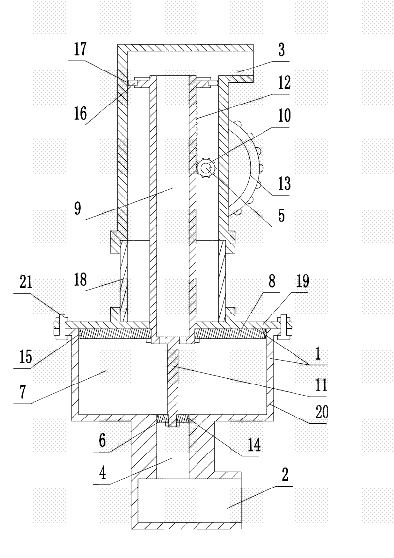
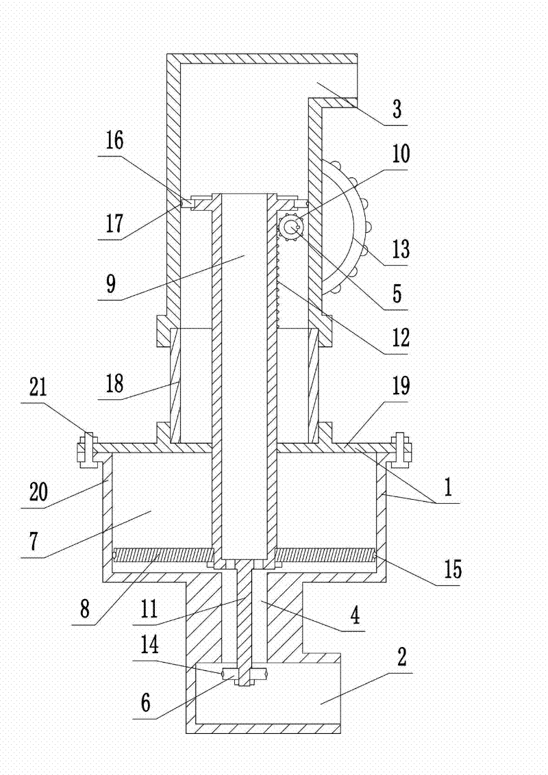
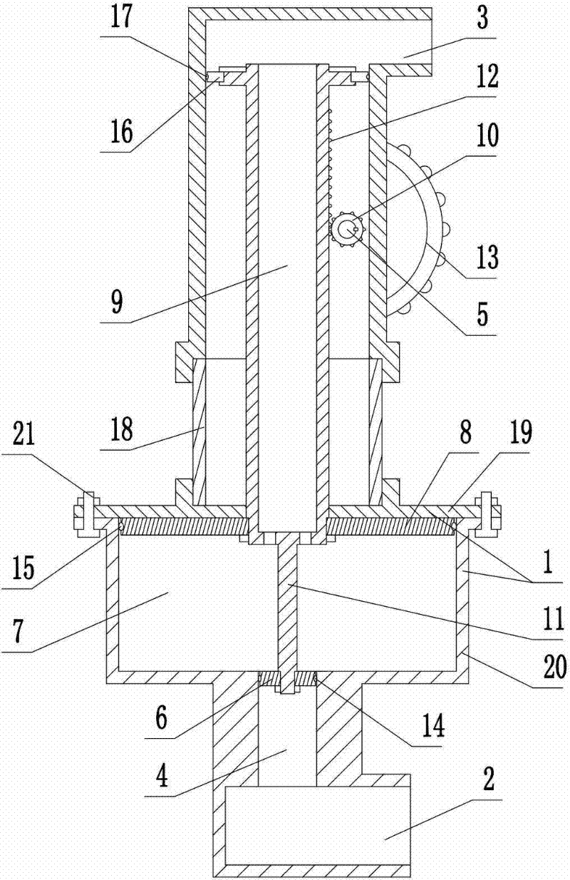
[0029] Such as figure 1 As shown, the water-saving antifreeze device includes a valve body 1, the lower part of the valve body 1 is fixedly connected with a water inlet pipe 2 communicating with the inner cavity of the valve body 1, and the water inlet pipe 2 is a round pipe and is arranged horizontally. The upper part of the valve body 1 is fixedly connected with a water outlet pipe 3 communicating with the inner cavity of the valve body 1, and the water outlet pipe 3 is also a round pipe and is arranged horizontally. A water supply valve seat 4 is arranged in the inner cavity of the valve body 1. The water supply valve seat 4 is a circular tubular cavity. The axis of the water supply valve seat 4 is vertically arranged. The water supply valve seat 4 is provided with a water supply valve plug 6 , which is in the shape of a disc, and the outer periphery of the water supply valve plug 6 is vertically slidingly matched with the inner wall of the water supply valve seat 4 . The ...


PUM


Abstract

The invention discloses a water-saving antifreezing device which comprises a valve body, wherein a water inlet pipe and a water outlet pipe are fixedly arranged on the valve body; a water supply valve seat for communicating the water inlet pipe and the water outlet pipe is arranged in an inner cavity of the valve body; a water supply valve plug is arranged on the inner wall of the water supply valve seat in a sliding seal matching way; a water storage cavity which is communicated with the inner cavity of the valve body is arranged between the water supply valve seat and the water outlet pipe;a water storage valve plug which is in sliding seal matching with the inner wall of the water storage cavity is installed in the water storage cavity; a connecting body for leading the water storage valve plug and the water supply valve plug to move synchronously is installed between the water storage valve plug and the water supply valve plug; a water pumping pipe for communicating the water storage cavity of the water storage valve plug nearby the water inlet pipe side with the water outlet pipe is installed on the water storage valve plug in a sealing way; the outer wall of the water pumping pipe nearby the water outlet pipe is in sliding seal matching with the inner wall of the valve body; and a drive device for driving the water pumping pipe to move up and down is installed on the valve body. The water-saving antifreezing device has the advantages of reasonable structure and convenience in operation, not only can prevent freezing but also can save water, is suitable for being used in various water supply occasions and is beneficial to improving the water supply reliability.

Description

technical field [0001] The invention relates to a water-saving antifreeze device. Background technique [0002] The valve is a control component in the fluid delivery system, which has functions such as cut-off, adjustment, flow diversion, reverse flow prevention, pressure stabilization, flow diversion or overflow pressure relief. Valves used in fluid control systems range from the simplest cut-off valves to various valves used in extremely complex automatic control systems, with a wide variety of varieties and specifications. Valves can be used to control the flow of various types of fluids such as air, water, steam, various corrosive media, mud, oil, liquid metal and radioactive media. In daily life, the valves we often see are all valves installed on water pipes. Traditional water pipe valves generally include a valve body, on which there are fixed water inlet pipes and outlet pipes connected to the inner cavity of the valve body, and a water supply valve seat connecti...

Claims


Application Information

Patent Timeline
Patent Type & Authority Patents(China)
IPC IPC(8): F16K3/24F16K27/04F16K31/54F16K31/60
Inventor 孙占标
Owner WEIFANG SANHUALI MACHINERY SCI & TECHCO
Why Eureka
Try Eureka