Device for automatically correcting accelerator pedal misoperation to braking operation by electrical and mechanical combination
An automatic correction and mechanical technology, applied in the field of automobile braking, can solve the problem of no refinement of the signal device, and achieve the effect of strong installation practicability, good reliability, and avoiding vicious traffic accidents.
- Summary
- Abstract
- Description
- Claims
- Application Information
AI Technical Summary
Problems solved by technology
Method used
Image
Examples
Embodiment 1
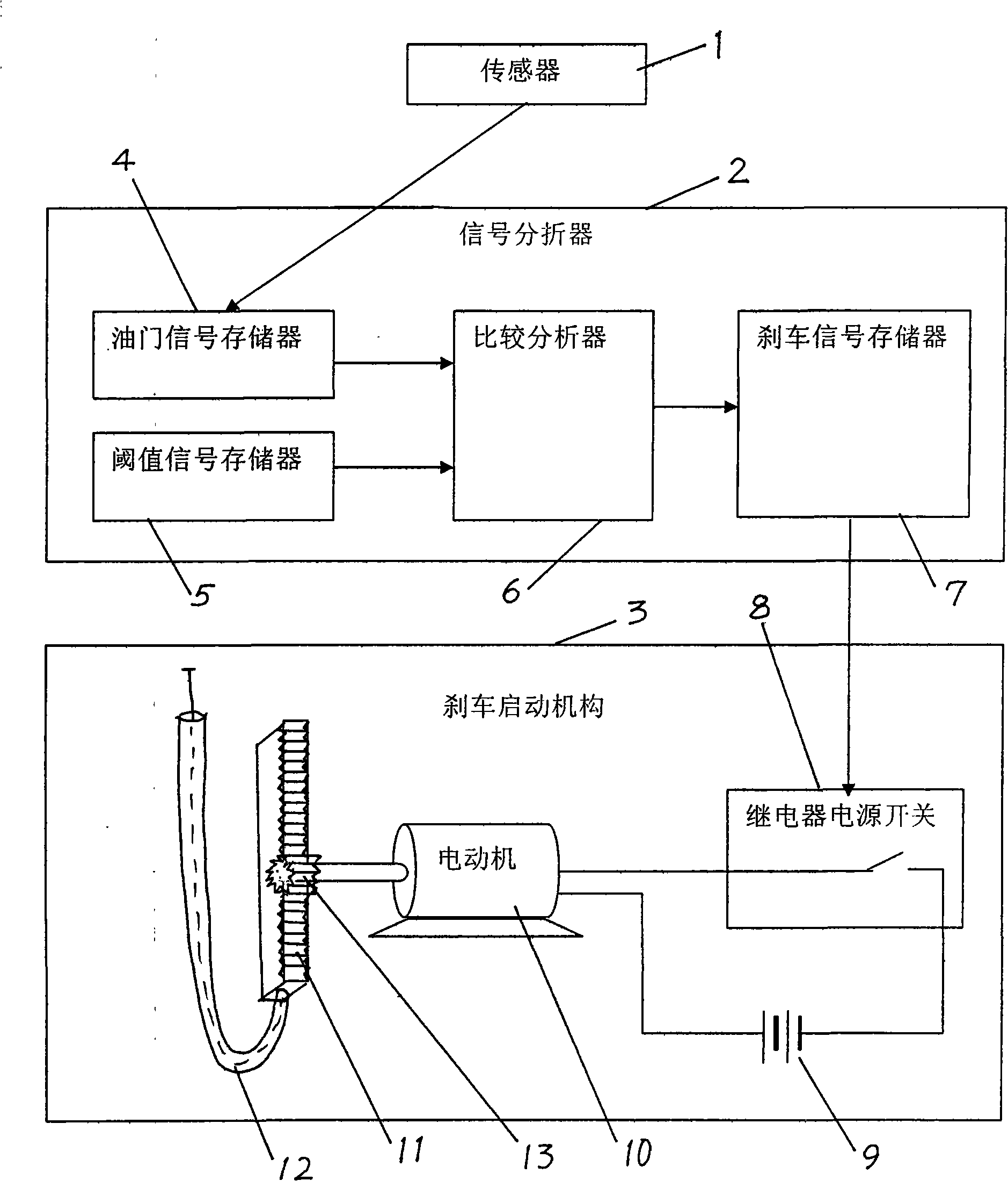
[0032] Embodiment 1, using the current signal of the collision sensor to compare the misstepped accelerator is corrected as a braking device
[0033] Such as figure 1 , sensor 1 selects and can feel the collision sensor of 10~50 kilograms for use to feel the action of stepping on the accelerator by mistake, and output the sensor that the electric current corresponding to the collision force of 10~50 kilograms is the sensor of 1~50 milliamps continuous change. The current signal output by the sensor 1 is the sensing signal, that is, the throttle signal.
[0034] Motor 10 selects direct current 12 volts for use, and power is the motor with governor of 20~80 watts.
[0035] Connect the sensor 1 with the signal analyzer 2, and transmit the throttle signal of the sensor 1 to the signal analyzer 2; connect the signal analyzer 2 with the brake activation mechanism 3, and the signal analyzer 2 transmits the electrical signal for starting the brake to the brake activation mechanism 3...
Embodiment 2
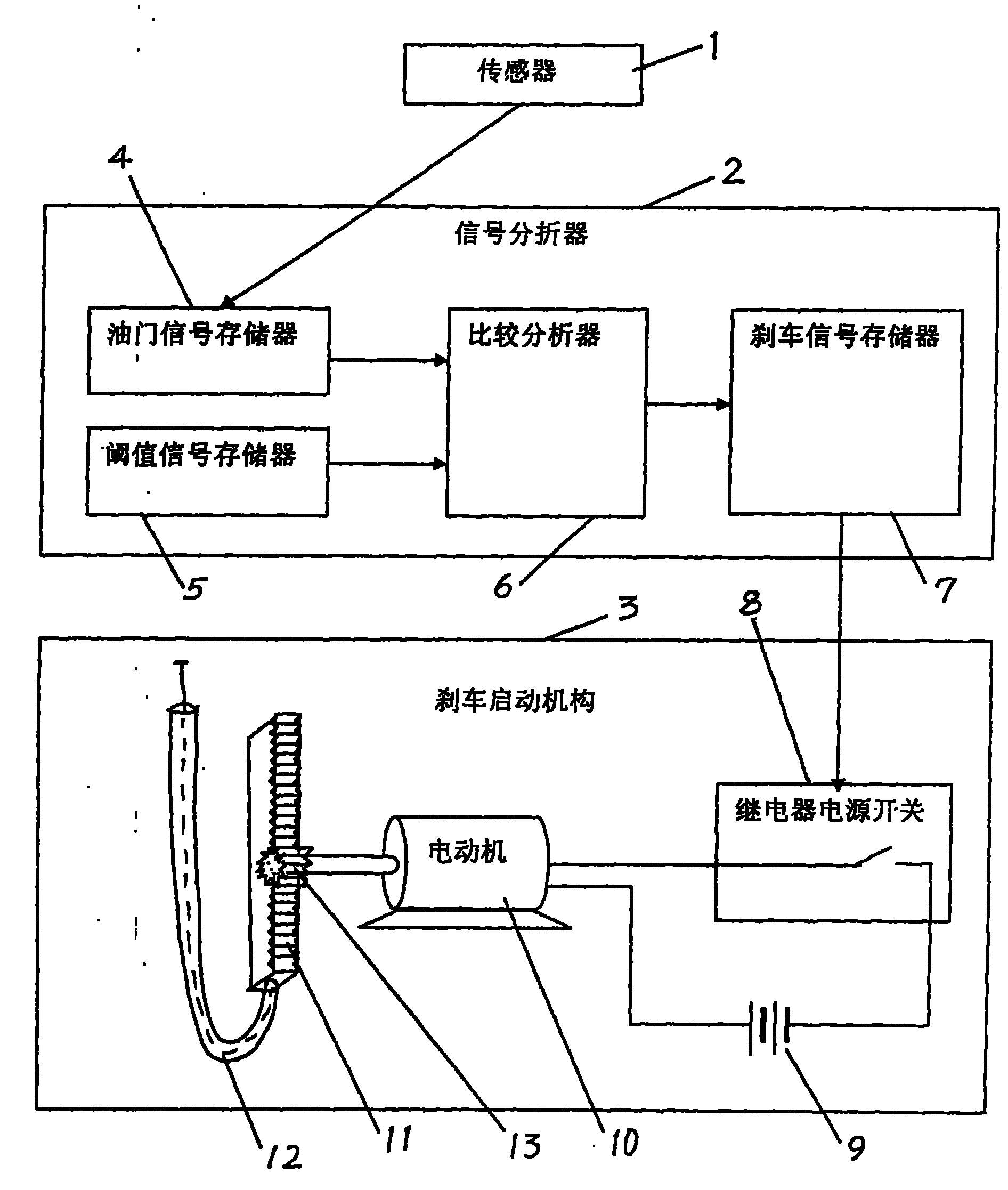
[0040] Embodiment 2, using the current signal of the speed sensor to compare the misstepped accelerator and correcting it as a braking device
[0041] Such as the connection and structural relationship of each component in Embodiment 1. The difference is:
[0042] The sensor 1 is changed to an acceleration sensor to sense the action of the accelerator pedal being misstepped, and outputs a sensor corresponding to the acceleration and continuously changing a current of 0.01 to 1.00 milliamperes. The current signal output by the sensor 1 is the sensing signal, that is, the throttle signal.
[0043] The starting braking threshold signal is stored in the threshold memory 5, and the starting braking threshold signal is selected from a current of 0.4 mA. As long as there is a comparison result that the accelerator signal value is greater than the current value of 0.4 mA, the comparison analyzer 6 outputs the start brake signal to the brake signal memory 7 . In a word, the signal t...
Embodiment 3
[0044] Embodiment 3, the power of the start-up brake signal is large, and the misstepping accelerator with better reliability is corrected as a brake device
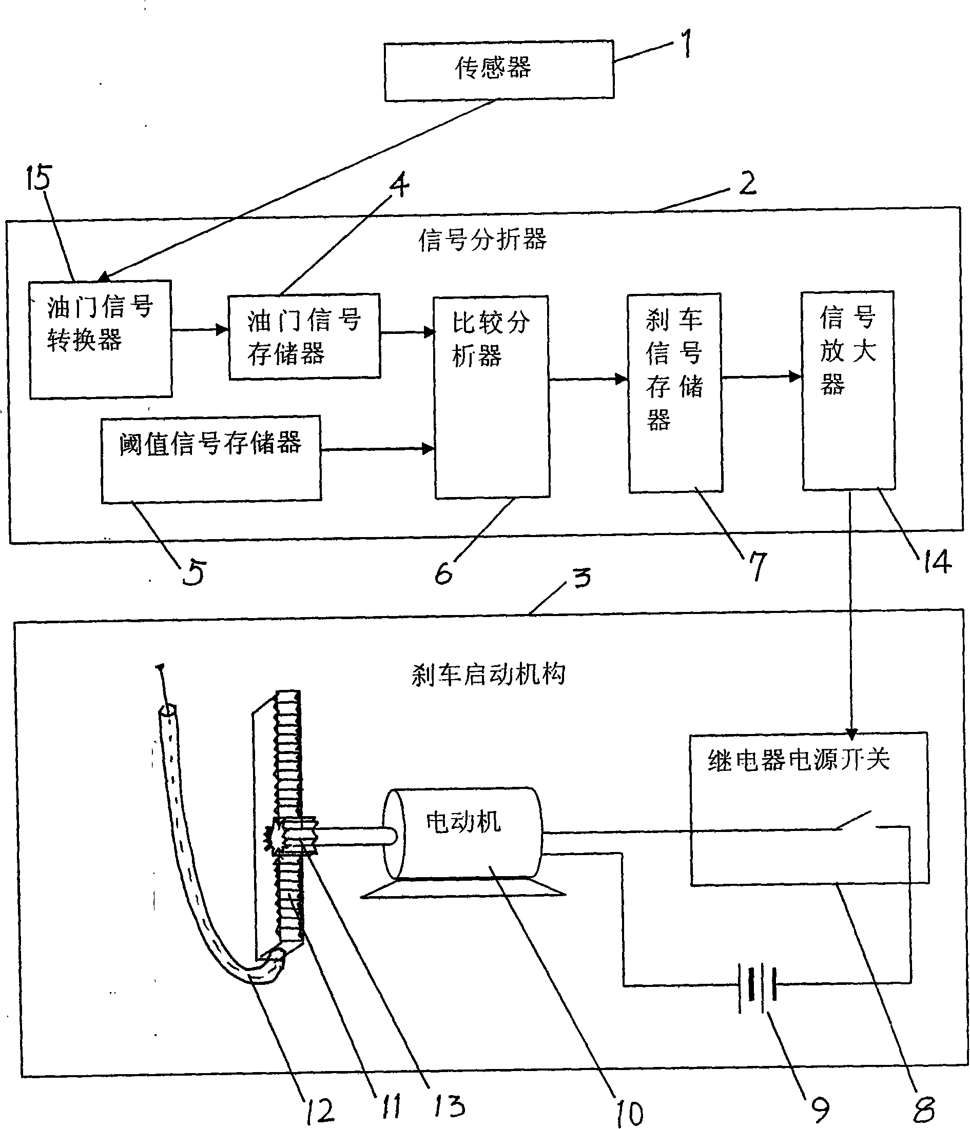
[0045] Such as figure 2 , the connection and structural relationship of each component of the brake activation mechanism 3, and the operation is the same as that of embodiment 1. However, a signal amplifier 14 is also added.
[0046] A signal amplifier 14 is connected in series between the braking signal memory 7 and the relay power switch 8 . The signal amplifier 14 amplifies the very weak starting and braking signal of the original signal power into a large energy starting and braking signal with 10.0 watts of electric power and transmits it to the relay power switch 8 .
[0047] The other throttle signal memory 4 divides the throttle signal into ten times and sends it to the comparison analyzer 6 within 0.005 seconds; and the brake signal memory 7 divides the start brake signal into multiple times and sends it to t...
PUM
 Abstract
Description
Claims
Application Information
 - R&D
- Intellectual Property
- Life Sciences
- Materials
- Tech Scout
- Unparalleled Data Quality
- Higher Quality Content
- 60% Fewer Hallucinations
Browse by: Latest US Patents, China's latest patents, Technical Efficacy Thesaurus, Application Domain, Technology Topic, Popular Technical Reports.
© 2025 PatSnap. All rights reserved.Legal|Privacy policy|Modern Slavery Act Transparency Statement|Sitemap|About US| Contact US: help@patsnap.com


