
Device and process for realizing denitration reaction and regeneration of SCR catalyst

A SCR catalyst and denitrification technology, applied in the direction of physical/chemical process catalysts, metal/metal oxide/metal hydroxide catalysts, chemical instruments and methods, etc., can solve the problems of large consumption, time-consuming and labor-consuming, high investment costs, etc.

Active Publication Date: 2011-07-06
ZHEJIANG TIANLAN ENVIRONMENTAL PROTECTION TECH
View PDF4 Cites 35 Cited by
  • Summary
  • Abstract
  • Description
  • Claims
  • Application Information

AI Technical Summary

Problems solved by technology

[0005] The above-mentioned patents have achieved good SCR catalyst regeneration effect, but there are still some problems: the Chinese invention patent CN101574671A needs to immerse the SCR catalyst in the regeneration solution, and it can be predicted that the required amount of reagents is large and the investment cost is also high; the Chinese invention Patent CN1768953A and US invention patent US7592283B2 need to be equipped with a special regeneration reaction device, so the catalyst needs to be removed from the denitration reactor first, which is time-consuming and labor-intensive, and the investment cost is high

Method used


Image

  • Device and process for realizing denitration reaction and regeneration of SCR catalyst
  • Device and process for realizing denitration reaction and regeneration of SCR catalyst

Examples


Embodiment 1

[0048] (1) SCR catalyst denitrification reaction

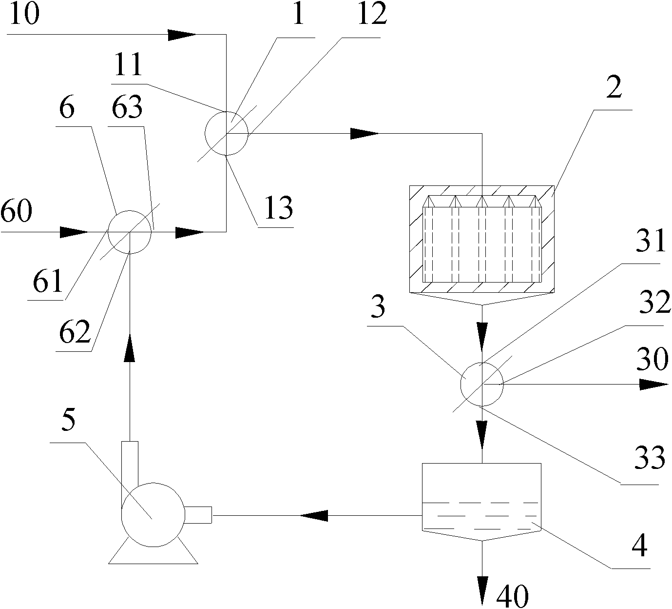
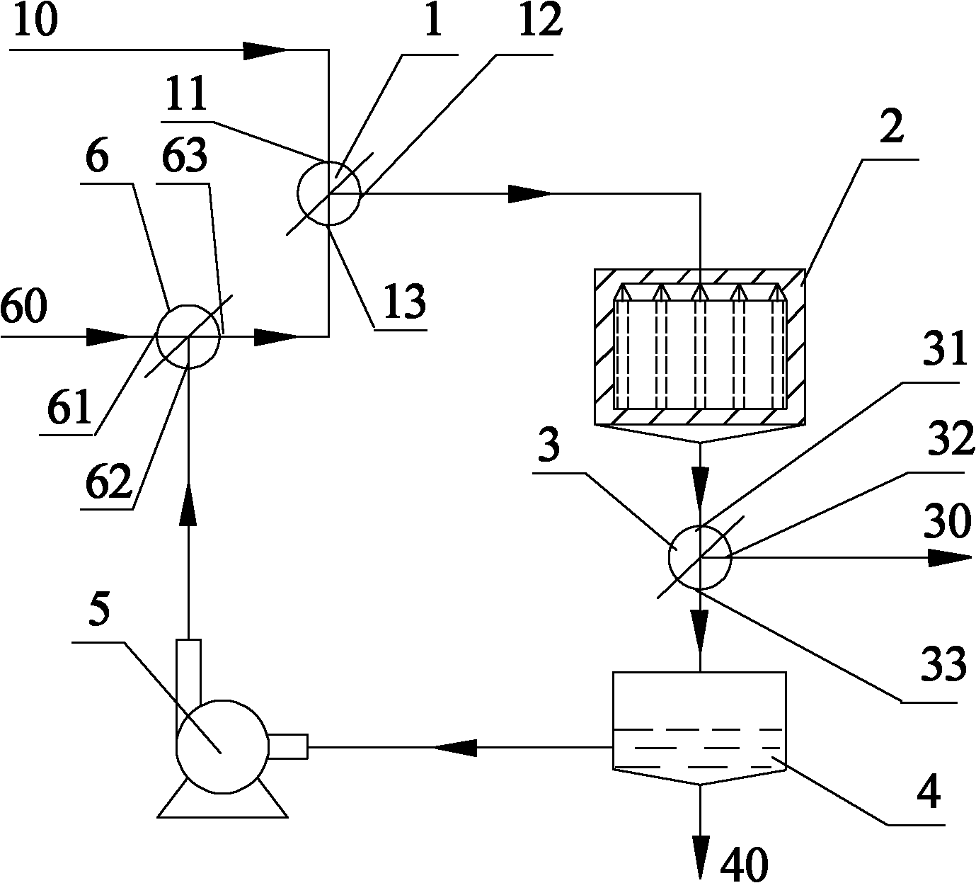
[0049] The flue gas is introduced from the flue gas input pipeline 10, and introduced into the SCR catalyst (V 2 o 5 -WO 3 / TiO 2 ) in the reactor 2, the denitrification reaction occurs, and the flue gas after denitrification is passed into the third three-way transfer valve 3, and the flue gas discharge pipeline 30 is used to achieve standard discharge.

[0050] SCR catalyst denitration reaction conditions: NH 3 / NO molar ratio 1.0, O 2 Concentration 5%, reaction temperature 330°C, gas space velocity 4000h -1 .

[0051] (2) SCR catalyst regeneration process

[0052] After the SCR catalyst is deactivated, it can be revived through the SCR catalyst regeneration process. The regeneration process is strictly operated according to the following process steps:

[0053] (I) Air purge

[0054] Oil-free dry compressed air (0.5MPa) is passed through the regeneration raw material input pipeline 60, the third three-way transfer ...

Embodiment 2

[0072] (1) SCR catalyst denitrification reaction

[0073] The flue gas is introduced through the flue gas input pipeline 10 and the first three-way transfer valve 1 into the 2 o 5 -MoO 3 / TiO 2 ) in the reactor, the denitrification reaction occurs, and the flue gas after denitrification is passed into the second three-way transfer valve 3, and the flue gas discharge pipeline 30 is used to achieve standard discharge.

[0074] SCR catalyst denitration reaction conditions: NH 3 / NO molar ratio 1.2, O 2 Concentration 8%, reaction temperature 380°C, gas space velocity 6000h -1 .

[0075] (2) SCR catalyst regeneration process

[0076] After the SCR catalyst is deactivated, it can be revived through the SCR catalyst regeneration process. The regeneration process is strictly operated according to the following process steps:

[0077] (I) Air purge

[0078] Same as Example 1, air purging time: 4h.

[0079] (II) pickling and alkali removal

[0080] Same as in Example 1, the a...


PUM


Abstract

The invention discloses a reactor device for realizing the denitration reaction and regeneration of a selective catalyst reduction (SCR) catalyst. The device comprises a reactor and a circulating pool, wherein a first three-way adapter valve which is connected with a flue gas input pipeline is arranged at an inlet of the reactor; a second three-way adapter valve is arranged between the reactor and the circulating pool; and through a circulating pump, the circulating pool is communicated with a third three-way adapter valve and then is communicated with the first three-way adapter valve. The invention also discloses a process for realizing the denitration reaction and regeneration of the SCR catalyst, wherein the denitration reaction of the SCR catalyst and the regeneration process of the SCR catalyst can be alternately performed in the same reaction device. A regeneration reaction device for the SCR catalyst and a denitration reaction device for the SCR catalyst are fused into one reaction device, the investment cost of equipment is effectively reduced, working procedures and expenses of the detachment and reinstallation of the SCR catalyst are avoided, and tim and labor are saved. Meanwhile, the process greatly reduces the using amount of acid solution and main agent supplement solution in regenerative raw materials.

Description

technical field [0001] The invention relates to the field of air pollution control, in particular to a device and a process for realizing denitrification reaction and regeneration of an SCR catalyst. Background technique [0002] Among the existing flue gas denitrification technologies, the most mature and commercially applied is the selective catalytic reduction method (NH 3 -SCR), which can be expressed as Reactive gas-solid reaction mode. It is well known that medium and high temperature NH 3 -SCR technology, the catalyst is the most important part, and its initial investment accounts for 40-60% of the total investment of the SCR system. Typical commercial SCR catalysts are V containing toxic heavy metal components 2 o 5 -WO 3 (MoO 3 ) / TiO 2 , in the actual coal-fired boiler, because the SCR catalyst is in a high-temperature and high-dust environment for a long time, the presence of alkali (earth) metal potassium K, sodium Na, and calcium Ca in the dust can cause...

Claims


Application Information

Patent Timeline
IPC IPC(8): B01J23/30B01J23/92B01D53/56B01D53/86
Inventor 莫建松鞠耀明程常杰吴忠标
Owner ZHEJIANG TIANLAN ENVIRONMENTAL PROTECTION TECH
Learn More