
Rotating platform

A technology of rotating table and rotating center, applied in the field of rotating table, can solve the problems of many intermediate links, low positioning accuracy, and slow response speed of the rotating table, and achieve fewer intermediate links, fast response speed, and reduce the difficulty of processing and assembly Effect

Active Publication Date: 2012-08-29
SHANGHAI MICRO ELECTRONICS EQUIP (GRP) CO LTD +1
View PDF6 Cites 0 Cited by
  • Summary
  • Abstract
  • Description
  • Claims
  • Application Information

AI Technical Summary

Problems solved by technology

[0004] The purpose of the present invention is to provide a rotary table to solve the problems of many intermediate links, slow response speed, and low positioning accuracy of the rotary table driven by a rotary motor and a screw mechanism in the photolithography process

Method used


Image

  • Rotating platform
  • Rotating platform
  • Rotating platform

Examples


Embodiment Construction

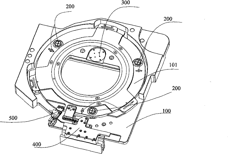
[0025] The rotary table proposed by the present invention will be described in further detail below in conjunction with the accompanying drawings and specific embodiments. Advantages and features of the present invention will be apparent from the following description and claims. It should be noted that the drawings are all in a very simplified form and use imprecise ratios, which are only used to facilitate and clearly assist the purpose of illustrating the embodiments of the present invention.

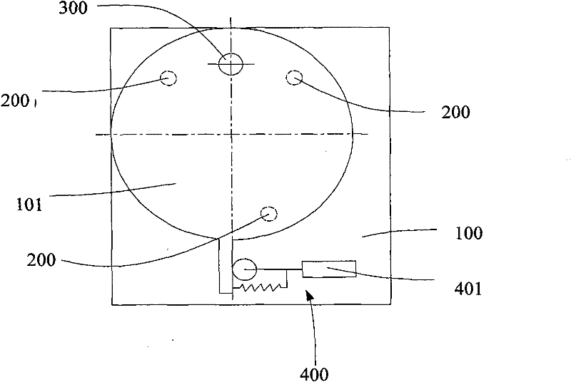
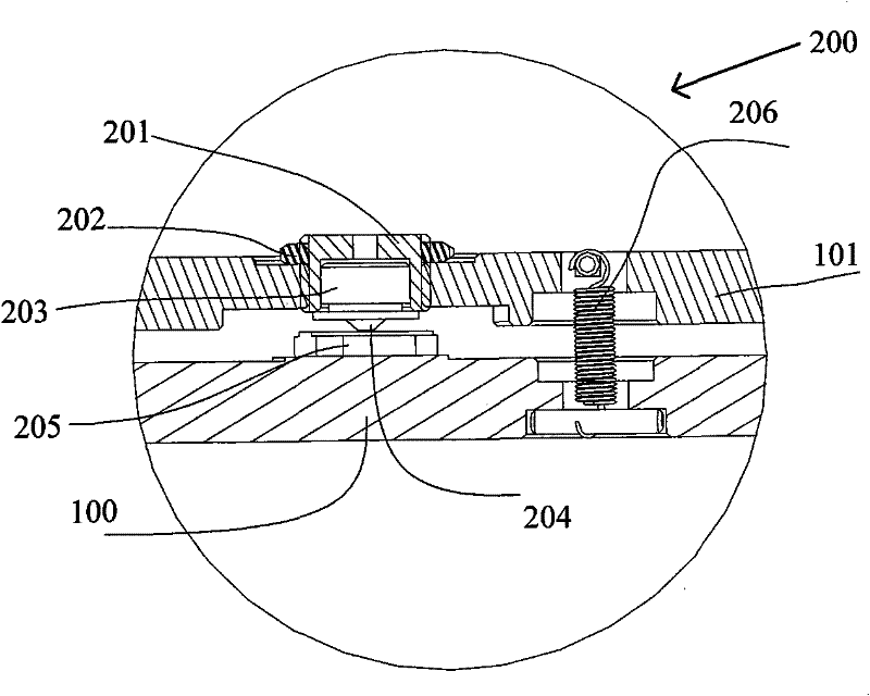
[0026] The core idea of ​​the present invention is to provide a rotary table, which can convert the linear motion of the linear motor into rotary motion through the cam follower by coupling the cam follower with the push plate, and the push plate is connected with the workbench. Thereby reducing the intermediate links and improving the response speed. At the same time, the rotation center positioning mechanism is made of a flexible mechanism, so there is no gap, the displacement is l...


PUM


Abstract

The invention discloses a rotating platform. The rotating platform comprises a workbench, a base plate, a vertical supporting mechanism, a rotation center positioning mechanism and a driving mechanism. The vertical supporting mechanism supports the workbench on the base plate and the height of the workbench can be adjusted. The rotation center positioning mechanism makes the workbench rotate along the vertical direction and determines the rotation center. The driving mechanism converts the linear motion of a linear electric motor into rotation motion. The intermediate links of the rotating platform provided by the invention are few, response speed is high and positioning accuracy is high.

Description

technical field [0001] The invention relates to the field of integrated circuit manufacturing, in particular to a rotary table used for carrying silicon wafers in a photolithography process. Background technique [0002] The development of microelectronics technology has promoted the replacement of computer technology, communication technology and other electronic information technologies, and plays an important leading and basic role in the revolution of the information industry. Production equipment plays a pivotal role in the entire microelectronics industry, and in the manufacturing equipment of microelectronic devices, the lithography equipment has the largest investment and the most critical role. With the improvement of integrated circuit integration, the positioning accuracy requirements of lithography machines are getting higher and higher, and in the positioning mechanism of lithography machines, the rotary table plays a very key role. "Six degrees of freedom prec...

Claims


Application Information

Patent Timeline
Patent Type & Authority Patents(China)
IPC IPC(8): G03F7/20B25H1/00
Inventor 周清华
Owner SHANGHAI MICRO ELECTRONICS EQUIP (GRP) CO LTD
Learn More