
Roller compacted concrete dam and slit forming method thereof

A technology of roller compacted concrete and seam forming, which is applied to the field of roller compacted concrete dams and their seams, and the field of roller compacted concrete arch dams. The effect of simple and convenient construction and simple structure

Active Publication Date: 2011-06-29
POWERCHINA ZHONGNAN ENG
View PDF5 Cites 16 Cited by
  • Summary
  • Abstract
  • Description
  • Claims
  • Application Information

AI Technical Summary

Problems solved by technology

[0005] In the early days of roller compacted concrete, there was a method of inducing holes to form seams. This method of forming seams was formed by manual brazing or pneumatic drilling after the concrete was rolled. , Concrete blocks the induction hole, this kind of seam formation method of filling sand in the induction hole is basically rarely used now
[0006] In the existing joint formation methods of roller compacted concrete dams that need to consider the transmission of pressure and shear force between transverse joints, the method of forming joints with prefabricated concrete blocks is basically used, but this kind of prefabricated concrete blocks weighs about 0.2t, which is relatively heavy and cannot be done manually. Moving requires special hoisting equipment to be installed on site. The site construction is relatively cumbersome, and concrete prefabricated blocks need to be stacked for every 0.3m high base layer. Other processes have a greater impact

Method used


Image

  • Roller compacted concrete dam and slit forming method thereof
  • Roller compacted concrete dam and slit forming method thereof
  • Roller compacted concrete dam and slit forming method thereof

Examples


Embodiment Construction

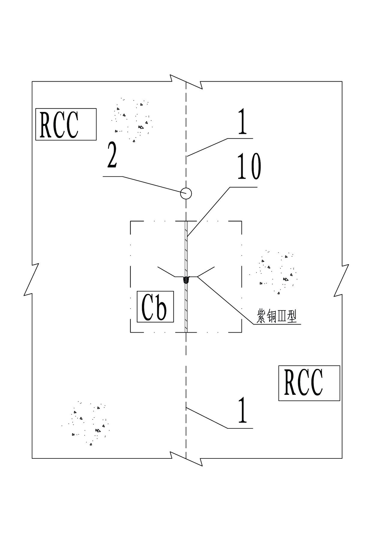
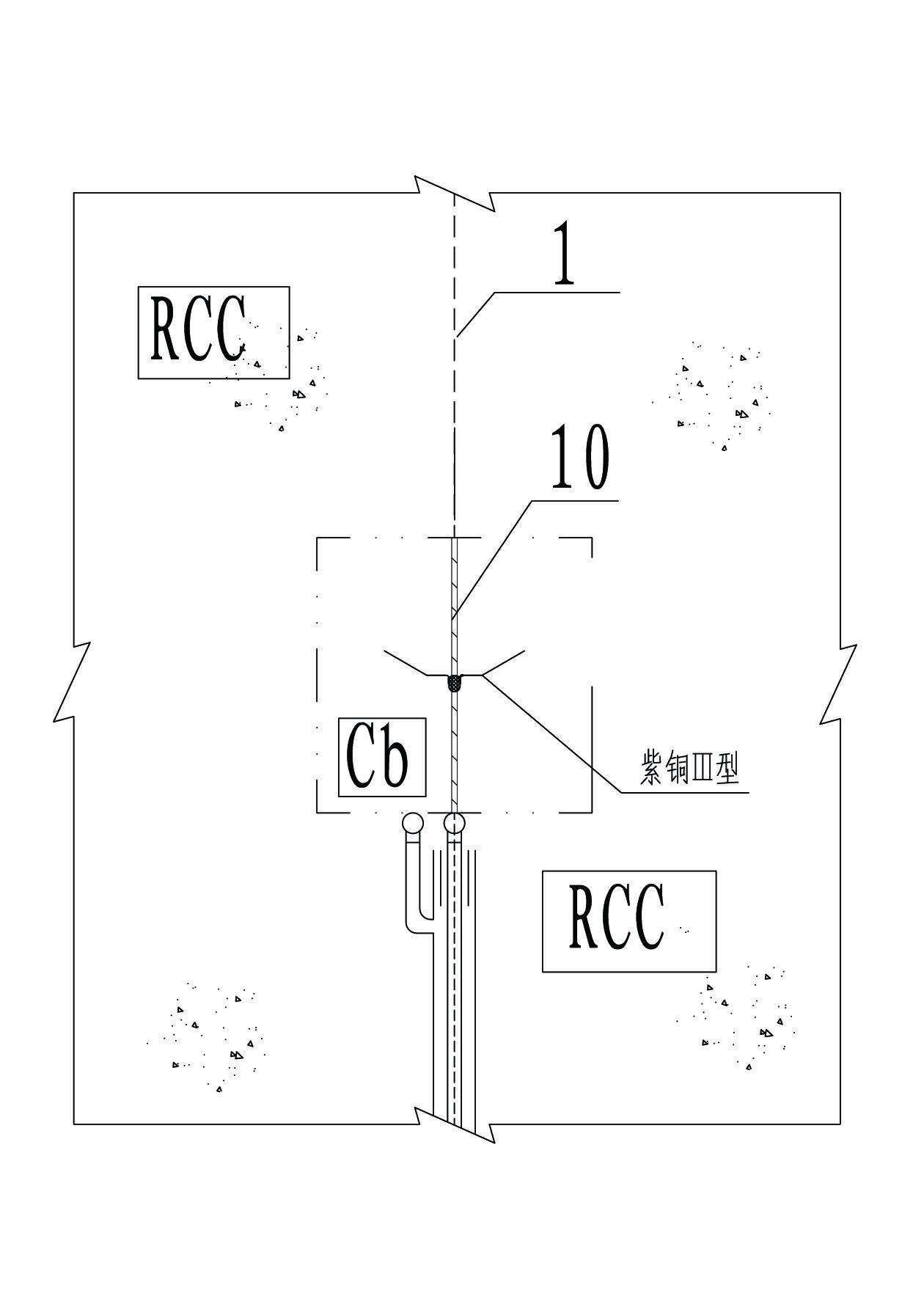
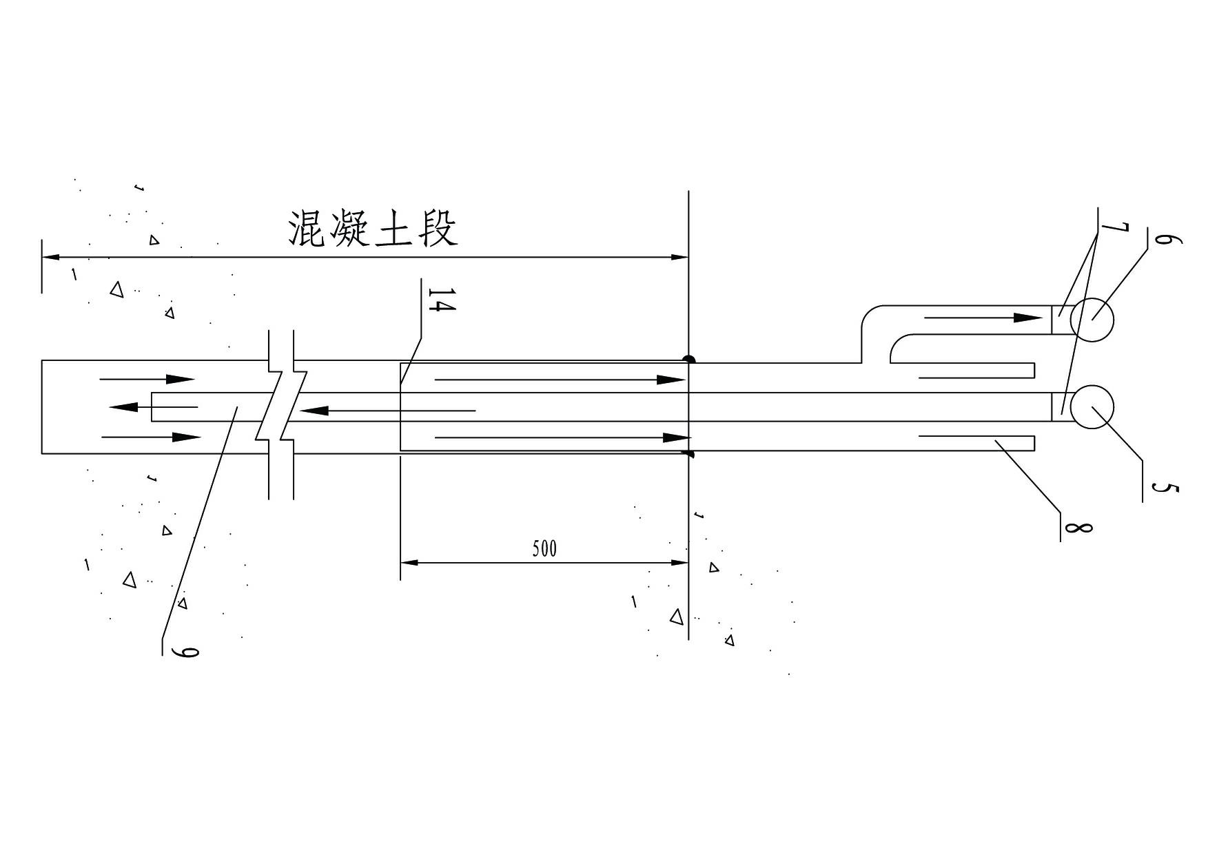
[0032] Such as figure 1 with 2 As shown, the distance between the induction holes 2 constructed along the transverse joint 1 is 0.75m, and the hole diameter is φ91; Asphalt hemp silk; a complete horizontal joint 1 irrigation area is about 30m long and 10m high; the diameter of the slurry feeding main pipe 5 and the slurry returning main pipe 6 are preferably 50mm, and the diameter of the slurry feeding branch pipe and the slurry returning branch pipe is preferably 33mm. The distance from the bottom of the induction hole is not more than 0.2m; the casing 14 of the grouting system is inserted 0.5m below the surface of the concrete silo, and the space between the casing 14 and the concrete induction hole is blocked with cotton yarn to avoid grout leakage; the slurry inlet branch pipe is inserted into the casing 14, and The pipe wall gap between the slurry main pipe 5 and the sleeve pipe 14 is closed with a rubber plug 8 .

[0033] Such as image 3 with 4 As shown, the constru...


PUM

PropertyMeasurementUnit
Diameteraaaaaaaaaa
Diameteraaaaaaaaaa

Abstract

The invention discloses a roller compacted concrete dam and a slit forming method thereof. The method comprises the following steps: pouring roller compacted concrete according to a conventional construction process, upwards guiding a vertical grout stop copper sheet together with the rise of a roller compacted layer, and drilling an induction hole in interval of concrete after a raising layer is upwards guided; arranging a grouting pipeline in the induction hole; and then arranging a horizontal grout stop copper sheet and the vertical grout stop copper sheet above the grouting pipeline, repeating the processes, and grouting a transverse slit through the grouting pipeline after the temperature of the roller compacted concrete is reduced to a stable temperature so as to form a roller compacted concrete transverse slit surface for transferring pressure and shearing force. Hoisting equipment is not needed, the warehouse surface construction is simple and convenient, and the transverse slit surface can transfer the pressure and the shearing force; and the method basically has no influence on the construction of large-scale roller compacted concrete of a warehouse surface, and is particularly suitable for slit formation of the roller compacted concrete dam with the transverse slit for transferring the pressure or the shearing force among the dam sections and the slit formation of a roller compacted concrete arch dam in the industries of water conservancy and hydroelectricity.

Description

technical field [0001] The invention relates to a roller-compacted concrete dam and its seam-forming method, in particular to a roller-compacted concrete dam body and a seam-forming method thereof which are suitable for pressure or shear force transmission in transverse joints between dam sections in the water conservancy and hydropower industries. Applicable to the joint formation of roller compacted concrete arch dams. Background technique [0002] In general, there are two basic methods for forming joints in roller compacted concrete dams: cutting joints and prefabricated formwork joints. In the early days, there was also the method of forming joints through induced holes. [0003] The seam cutting method is generally to cut the concrete of the green layer directly along the horizontal seam with a seam cutting machine after the roller compacted concrete is rolled, and fill the seam with colored strip cloth or zinc iron sheet or Place dry sand spacers directly in the join...

Claims


Application Information

Patent Timeline
IPC IPC(8): E02B3/16E02B7/08E02B7/12E02D15/00
Inventor 冯树荣潘江洋张永涛
Owner POWERCHINA ZHONGNAN ENG
Learn More