


Quick Research
Generate reliable direction feasibility study reports for your R&D in just a few steps.

Technical Q&A
Discover and master advanced knowledge NOW. Basics, ideas, possibilities, all at once.

Find Solutions
As an expert in R&D theories, this can generate solutions to your technical problems instantly.

Evaluate Feasibility
Analyze your overall solution with one click, know your potential R&D risks in advance.

Monitor Landscape
Get weekly tech updates, stay abreast of the latest tech innovations and key insights.
Method and device for measuring hole diameter of optical fiber with hole, and method and device for manufacturing optical fiber with hole
A measuring method and a manufacturing method technology, which can be applied to measurement devices, optical devices, testing optical fiber/optical waveguide equipment, etc., can solve problems such as the decline of optical fiber productivity, and achieve the effect of reducing deviation and ensuring optical characteristics.
- Summary
- Abstract
- Description
- Claims
- Application Information
AI Technical Summary
Problems solved by technology
Method used
Image

Examples
no. 1 approach
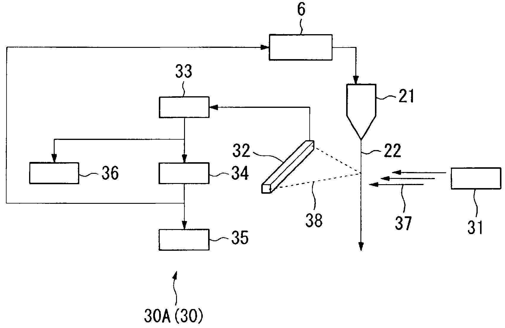
[0060] (Equipment for Measuring Hole Diameter of Optical Fiber with Holes and Manufacturing Equipment for Optical Fibers with Holes)
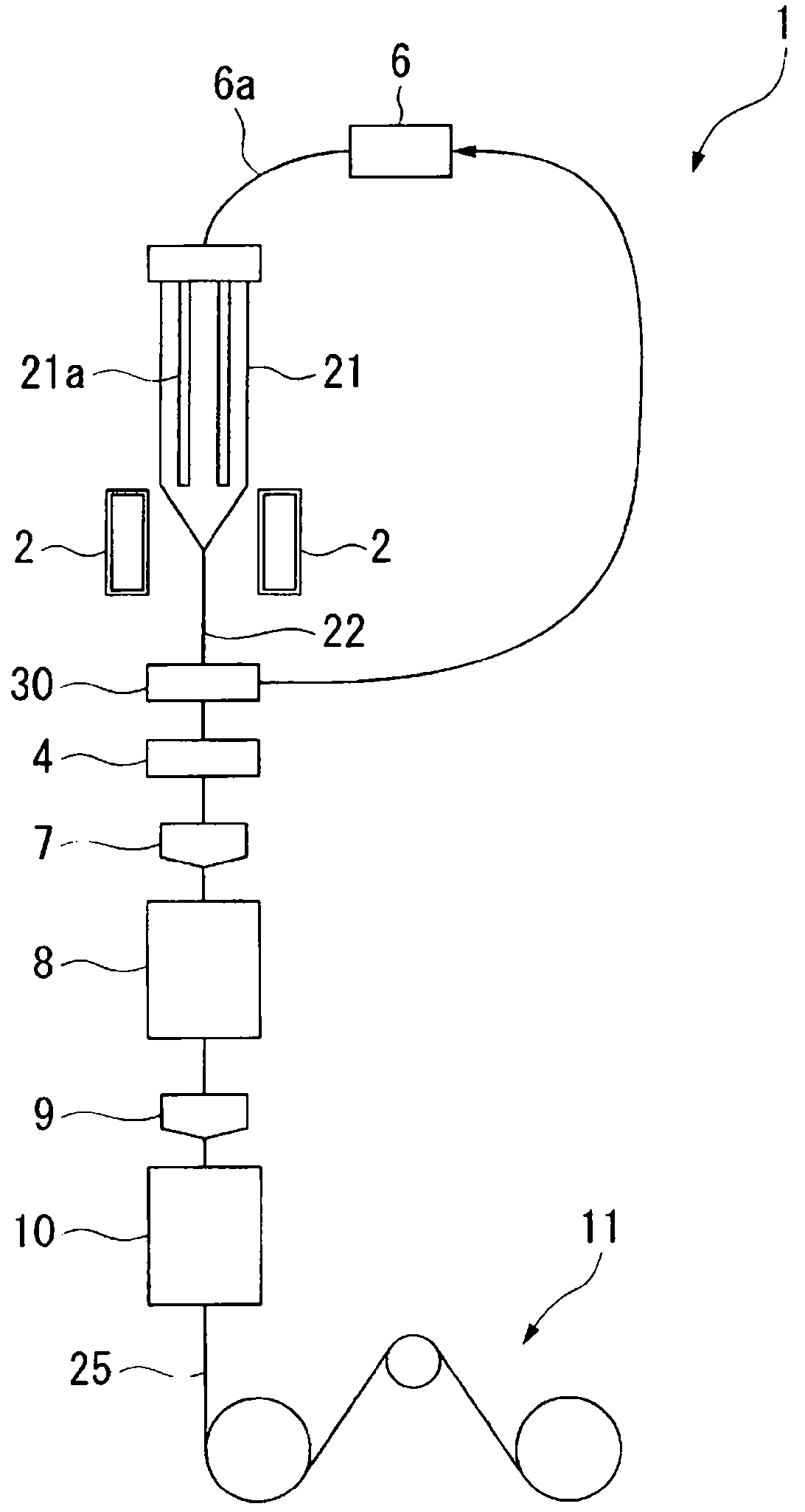
[0061] Hereinafter, the apparatus for measuring the diameter of a void in an optical fiber with a void and the apparatus for manufacturing an optical fiber with a void according to a first embodiment of the present invention will be described in detail with reference to the drawings. figure 1 It is a schematic configuration diagram showing a hole diameter measuring device 30A ( 30 ) of an optical fiber with a hole (hereinafter simply referred to as a hole diameter measuring device) according to the first embodiment of the present invention. figure 2 It is a schematic configuration diagram showing an optical fiber manufacturing apparatus 1 with holes (hereinafter simply referred to as an optical fiber manufacturing apparatus) according to an embodiment of the present invention. The optical fiber manufacturing apparatus 1 of this embodiment has...
no. 2 approach
[0112] Figure 9C It is a graph showing an example of a scattering intensity pattern obtained by the method of measuring the hole diameter of an optical fiber with holes according to the second embodiment of the present invention.
[0113] The method of measuring the void diameter of the present embodiment differs from the method of measuring the void diameter of the first embodiment in that the scattering intensity pattern obtained from an optical fiber with voids and the scattering intensity pattern obtained from an optical fiber without voids are used. Calculate the width W of the central dark part from the difference spectrum.
[0114] In addition, when manufacturing an optical fiber with a hole, it is the same as the above-mentioned first embodiment except that the width W of the central dark portion is obtained using the difference spectrum. At this time, in the calculation unit 34 of the measuring device 30 of the void diameter, programming is performed so as to obtain...
no. 3 approach
[0120] Figure 10 It is a figure which schematically shows the measurement apparatus 30B (30) of the pore diameter used for the measurement method of the pore diameter which concerns on the 3rd embodiment of this invention. The pore diameter measuring device 30B of this embodiment differs from the first embodiment in that a plurality of irradiation devices 31 ( 31A, 31B) and detection units 32 ( 32A, 32B) are provided. These detection units 32A and 32B are connected to the same signal processing unit 33 . In the illustrated example, a case where two irradiation devices 31 and two detection units 32 are respectively provided was shown, but the number is not particularly limited to this number.
[0121] In the method for measuring the pore diameter (the pore diameter measuring device 30A) of the first embodiment described above, the width W of the central dark portion of the scattering intensity pattern 43 changes depending on the direction in which the parallel light ray 37 is...
PUM
 Abstract
Description
Claims
Application Information
 - R&D Engineer
- R&D Manager
- IP Professional
- Industry Leading Data Capabilities
- Powerful AI technology
- Patent DNA Extraction
Browse by: Latest US Patents, China's latest patents, Technical Efficacy Thesaurus, Application Domain, Technology Topic, Popular Technical Reports.
© 2024 PatSnap. All rights reserved.Legal|Privacy policy|Modern Slavery Act Transparency Statement|Sitemap|About US| Contact US: help@patsnap.com