
Micro-flow valve and direct liquid fuel battery fuel supply system

A micro-flow, flow valve technology, applied in fuel cells, fuel cell additives, fuel cell control and other directions, can solve the problems of high cost and difficult to reduce costs, improve efficiency, ensure safety, reduce parasitic power consumption and manufacturing cost effect

Active Publication Date: 2013-06-19
DALIAN INST OF CHEM PHYSICS CHINESE ACAD OF SCI
View PDF5 Cites 0 Cited by
  • Summary
  • Abstract
  • Description
  • Claims
  • Application Information

AI Technical Summary

Problems solved by technology

At present, there are still few manufacturers that can guarantee the operating life of the order of magnitude of micro-fuel pumps and micro-solenoid valves.
In addition, most of micro fuel pumps and micro solenoid valves are manufactured based on MEMS technology, which are still under development and expensive
However, there are no mature products for online liquid fuel concentration sensors. Most of the concentration sensors that have been researched and developed are based on electrochemical principles. Since this type of sensor needs to use noble metal catalysts, it is difficult to reduce the cost, and the reliability needs further investigation.

Method used


Image

  • Micro-flow valve and direct liquid fuel battery fuel supply system
  • Micro-flow valve and direct liquid fuel battery fuel supply system
  • Micro-flow valve and direct liquid fuel battery fuel supply system

Examples


Embodiment 1

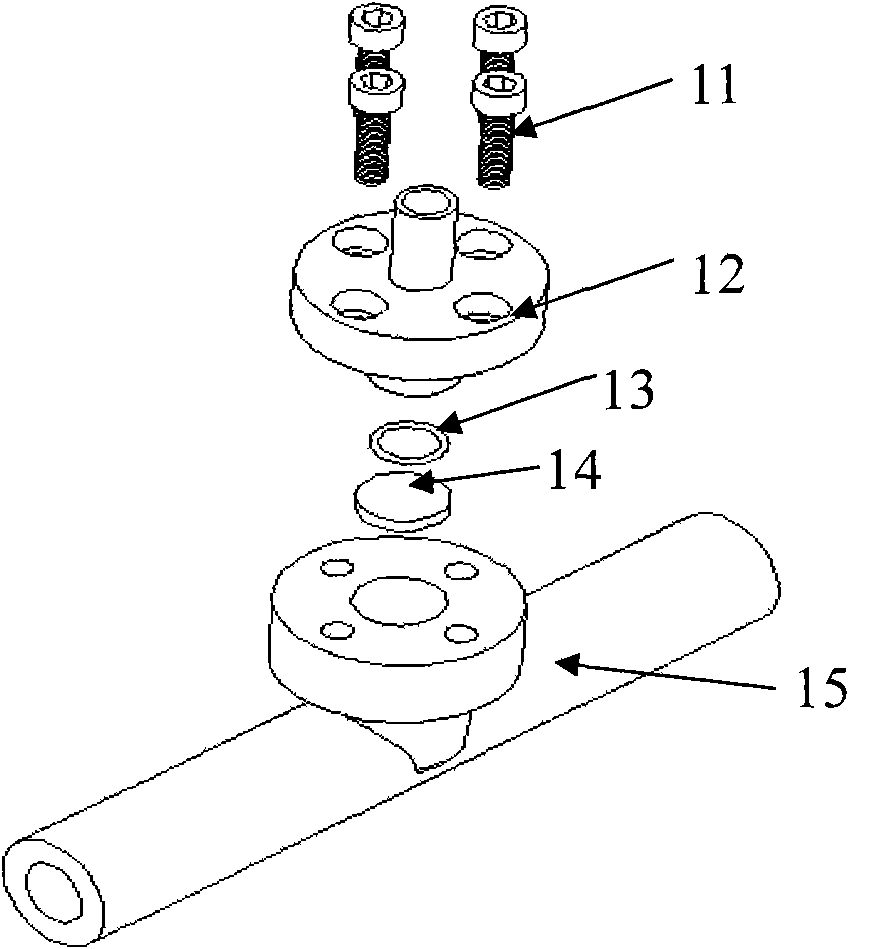
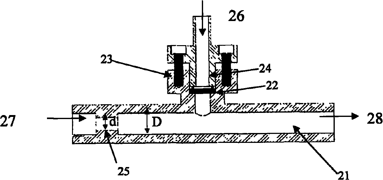
[0034] A liquid micro flow valve, its structure is as figure 1 with figure 2 shown. It is mainly composed of four parts: fuel inlet valve body 12 , sealing ring 13 , microporous membrane 14 , and fuel outlet valve seat 15 . The microporous membrane 14 is placed at the bottom of the side branch concave hole 22 of the valve seat 15, the fuel inlet valve body 12 is buckled on the flange 23 of the valve seat 15 by the screw 11, and the raised stop 24 of the fuel inlet valve body 12 is pressed The sealing ring 13 realizes the sealing between the microporous membrane, the valve seat and the valve body stop. The main pipe 21 of the valve seat 15 communicates with the flange 23, and the inlet of the main pipe 21 is provided with a section of throat pipe 25 to increase the liquid suction resistance of the inlet.

[0035] The microporous membrane used in the above-mentioned liquid micro-flow valve is non-hydrophilic, such as PVDF membrane and PTFE membrane, the pore diameter of whic...


PUM

PropertyMeasurementUnit
lengthaaaaaaaaaa
areaaaaaaaaaaa

Abstract

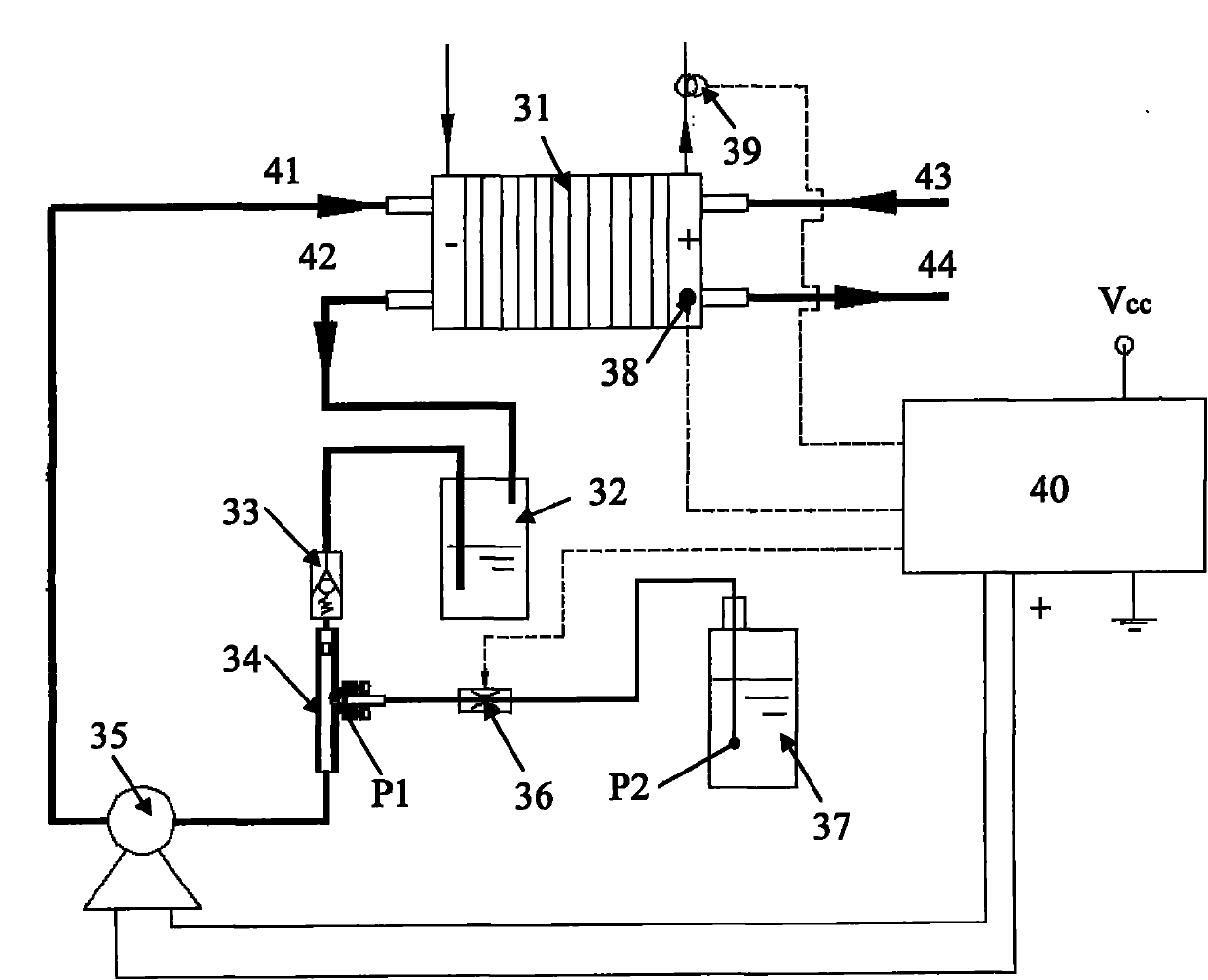
The invention relates to a micro-flow valve and a direct liquid fuel battery fuel supply system. The micro-flow valve comprises a fuel inlet valve body and a fuel outlet valve seat, wherein a microporous membrane is arranged on a fuel flowing channel between the fuel inlet valve body and the fuel outlet valve seat; and namely at the joint, where the microporous membrane is placed, of the valve body and the valve seat, solution flow is limited at a required flow level of a direct liquid fuel battery system by using the microporous membrane. The direct liquid fuel battery fuel supply system constructed by utilizing the micro-flow valve is matched with the micro-flow valve through a circulation pump; and the regulation and the control of the cathode solution concentration of a direct liquid fuel battery can be realized by taking a galvanic pile current and a galvanic pile temperature as parameters and procedurally controlling a power supply voltage of a fuel pump. Components such as a liquid concentration sensor, a micropump, an electromagnetic valve and the like used in a common liquid fuel battery system are reduced, the integration level and the reliability of the system are improved, and the parasitic power consumption and the manufacturing cost of the system are reduced.

Description

technical field [0001] The invention relates to a liquid micro-flow valve and a direct liquid fuel cell anode fuel supply system constructed by using the valve. The micro-flow valve limits the maximum supply of anode fuel and ensures the safety of the direct liquid fuel cell system; the fuel supply system based on this valve reduces the number of fuel concentration sensors used in the traditional direct liquid fuel cell anode fuel supply system. Pumps, micro solenoid valves and other components improve the integration and reliability of the system. Background technique [0002] A direct liquid fuel cell is an electrochemical reaction device that directly converts the chemical energy in liquid fuel into electrical energy. Liquid fuels (including alcohol fuels, formic acid and acetic acid, etc.) have high specific energy density and have broad application prospects in the field of portable mobile power sources. [0003] In order to improve the fuel utilization rate of the sy...

Claims


Application Information

Patent Timeline
Patent Type & Authority Patents(China)
IPC IPC(8): H01M8/02H01M8/04H01M8/04298H01M8/1009
CPCY02E60/50Y02P70/50
Inventor 孙公权陈利康孙海赵钢秦兵
Owner DALIAN INST OF CHEM PHYSICS CHINESE ACAD OF SCI
Learn More