Cross chain link jewelry molding machine

A technology of jewelry forming machine and cross link, applied in clothing, watch chain, decorative chain and other directions, can solve the problems of affecting the quality of finished products, low production efficiency, cumbersome production process, etc., to reduce production costs, high degree of automation, and equipment structure. compact effect

Active Publication Date: 2011-06-15
SHANDONG MOKINGRAN JEWELRY
View PDF6 Cites 13 Cited by
  • Summary
  • Abstract
  • Description
  • Claims
  • Application Information

AI Technical Summary

Problems solved by technology

[0002]Precious metal jewelry is more and more favored by consumers due to its small size and changeable shape, and the market demand is also increasing. Relatively cumbersome, if you rely on traditional handmade, unless you hire a lot of labor, it can no longer meet the needs of the market
For example, the common cross-link necklaces on the market are usually done by hand. First, cut the cross metal wire to a standard length, then cut off two sides at both ends of the cross wire, and then cut off the two sides without sides. A small hole is punched on each end. In order to make the cross link more beautiful to wear, light can be reflected from multiple angles. Therefore, after the cross link is made and shaped, there is a twisting process to fix the two ends of the cross link. , and then relatively rotated 180 degrees so that the middle part is twisted into a spiral shape. Due to the uneven level of the operator, the shapes of the jewelry produced are also different, which affects the quality of the final product, and manual production requires a lot of labor, time-consuming and laborious. , the production efficiency is very low

Method used


Image

  • Cross chain link jewelry molding machine
  • Cross chain link jewelry molding machine
  • Cross chain link jewelry molding machine

Examples


Embodiment Construction

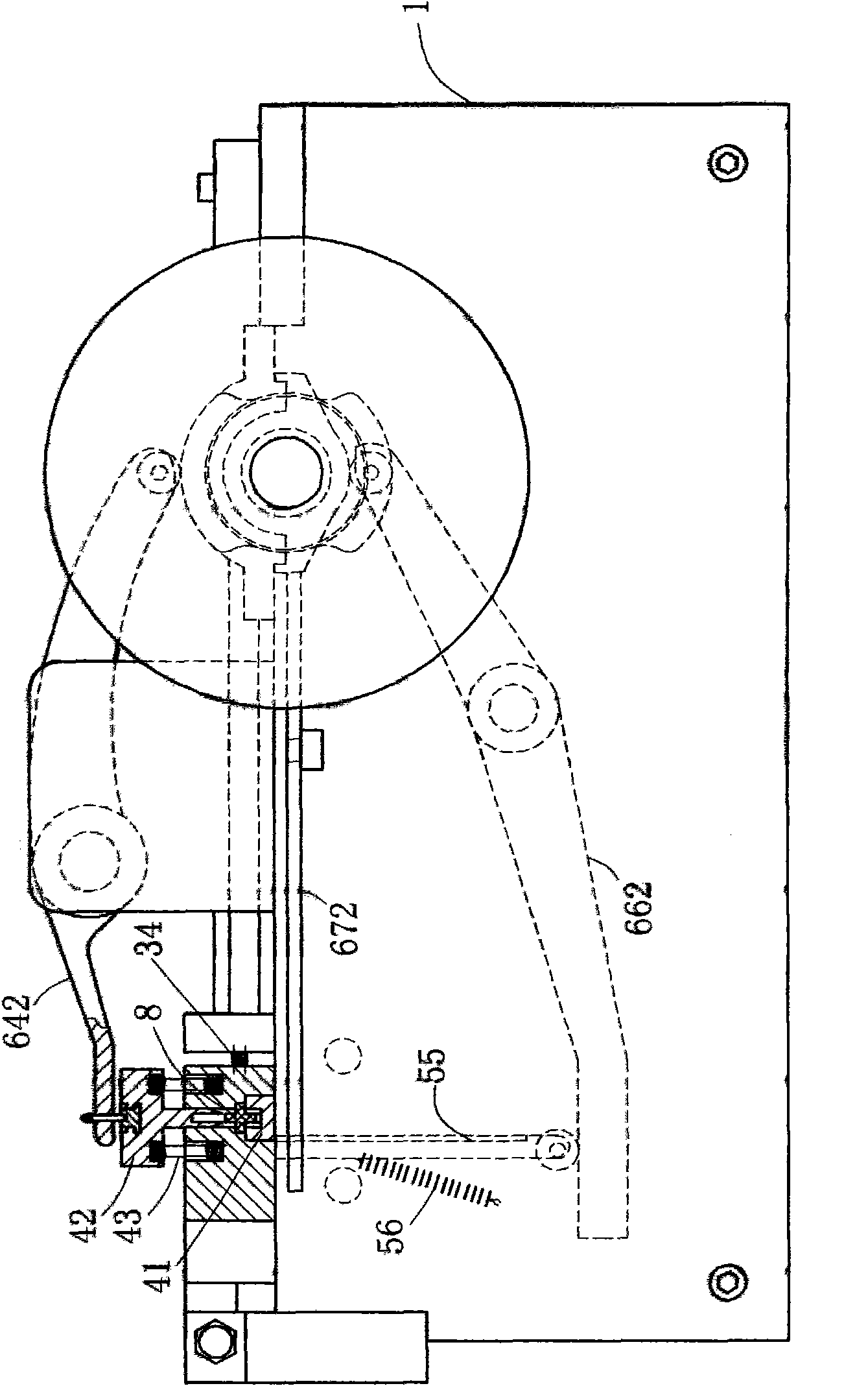
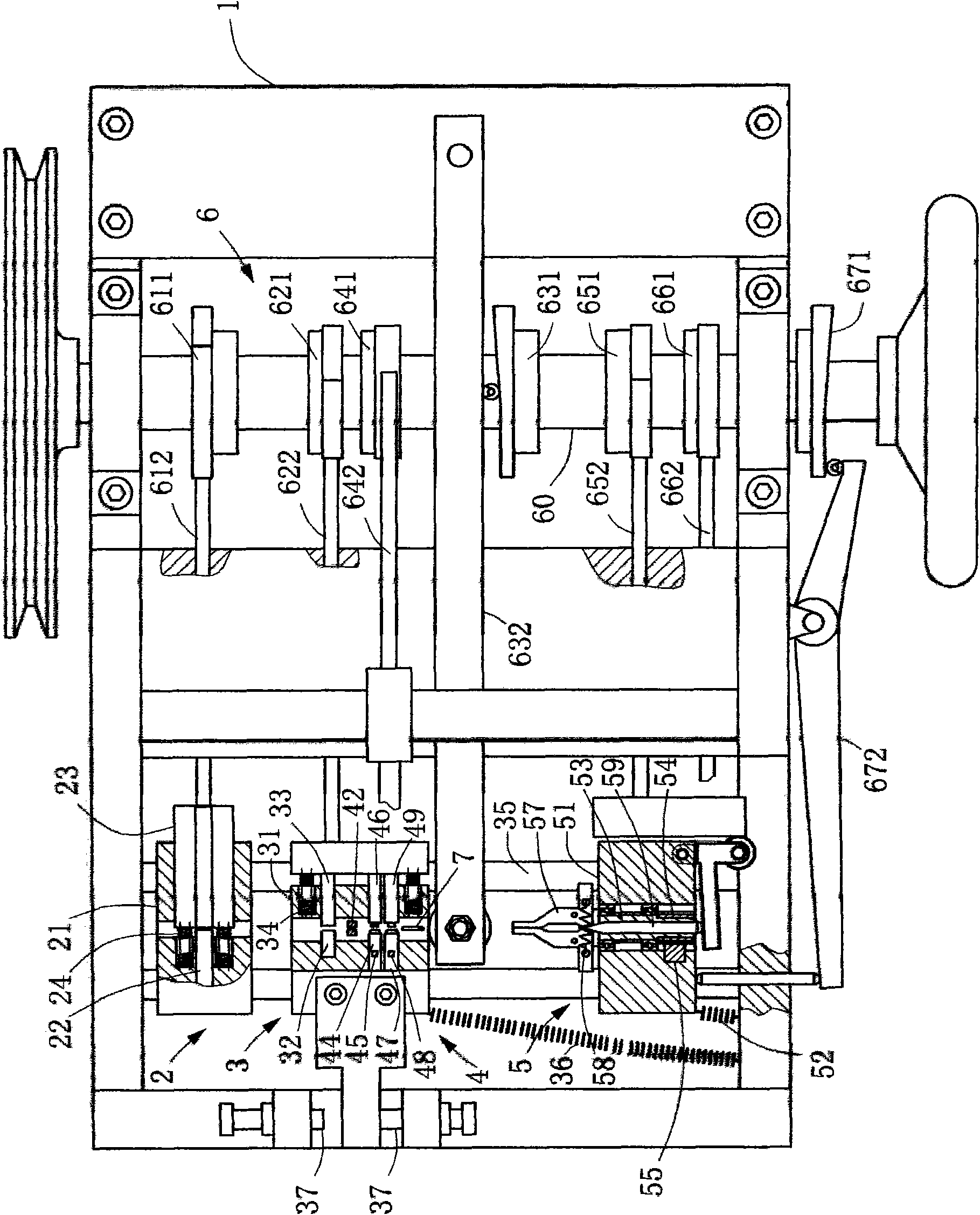
[0024] Such as figure 1 and figure 2As shown, a cross link jewelry forming machine mainly includes a frame 1, a feeding device, a progressive stamping die 4, a twisting device 5 and a driving device 6. Wherein, the feeding device is installed on the frame 1, and is used to convey the cross wire 8 to the downstream step by step; the progressive stamping die 4 is installed on the frame 1 and is located at the downstream of the feeding device position, for cutting off a section of the two sides of the cross wire 8 and punching two holes at the position without sides; the twisted flower device 5 is installed on the frame 1 And be located at the downstream position of described progressive stamping die 4, be used for clamping one end of the cross wire 8 of cutting and rotate an angle; Described driving device 6 is used for coordinating described feeding device, progressive stamping die 4 and the twisted flower device 5 act in sequence.

[0025] The feeding device mainly include...


PUM


Abstract

The invention discloses a cross chain link jewelry molding machine, which belongs to the technical field of jewelry processing machinery. The cross chain link jewelry molding machine mainly comprises a feeding device, a progressive punching die and a twisting device which are driven by a driving device and are sequentially arranged on a main frame, wherein the feeding device is used for gradually conveying a cross metal wire to the downstream; the progressive punching die is used for cutting off a section of each of both sides of the cross metal wire, punching two holes at positions without the sides and then cutting off; and the twisting device is used for clamping one end of the cut cross metal wire and rotating an angle. The cross chain link jewelry molding machine can produce cross metal wires into cross chain link jewelries, replace the conventional manual manufacturing, and improve the production efficiency of jewelry processing.

Description

technical field [0001] The invention relates to the technical field of jewelry processing machinery, in particular to a molding machine for making chain link jewelry by using cross metal wires. Background technique [0002] Precious metal jewelry is more and more favored by consumers because of its small size and changeable shape. The market demand is also increasing, and the production process is relatively cumbersome. If you rely on traditional hand-made, unless you hire a lot of labor , can no longer meet the needs of the market. For example, the common cross-link necklaces on the market are generally done by hand. First, cut the cross metal wire to a standard length, then cut off two sides at both ends of the cross wire, and then cut off the two sides without sides. A small hole is punched at each end. In order to make the cross link more beautiful to wear, light can be reflected from multiple angles. Therefore, after the cross link is made and shaped, there is a twisti...

Claims


Application Information

Patent Timeline
IPC IPC(8): A44C27/00A44C11/00
Inventor 王忠善
Owner SHANDONG MOKINGRAN JEWELRY
Why Eureka
Try Eureka