


Quick Research
Generate reliable direction feasibility study reports for your R&D in just a few steps.

Technical Q&A
Discover and master advanced knowledge NOW. Basics, ideas, possibilities, all at once.

Find Solutions
As an expert in R&D theories, this can generate solutions to your technical problems instantly.

Evaluate Feasibility
Analyze your overall solution with one click, know your potential R&D risks in advance.

Monitor Landscape
Get weekly tech updates, stay abreast of the latest tech innovations and key insights.
Rotary type weld beading removing knife suitable for grooved steel rail and method for hanging and fetching weld-beading removing knife
A technology of trough-shaped rails and tumor-pushing knives, which is applied in auxiliary devices, auxiliary welding equipment, welding/cutting auxiliary equipment, etc., can solve the problems of inconvenient hanging of knives and inability to take out knives conveniently, and achieve the effect of coherent action
- Summary
- Abstract
- Description
- Claims
- Application Information
AI Technical Summary
Problems solved by technology
Method used
Image

Examples
Embodiment 1
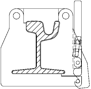
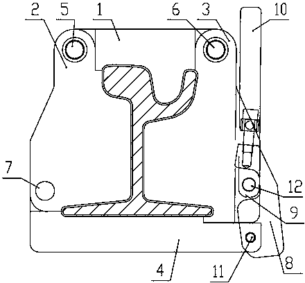
[0025] The rotary tumor-removing knife suitable for grooved rails includes a top knife 1, a left waist knife 2, a right waist knife 3 and a bottom knife 4, and the left waist knife 2 and the right waist knife 3 are respectively arranged on the left and right sides of the top knife 1, The bottom knife 4 is located below the top knife 1, and it is characterized in that: the two ends of the top knife 1 are provided with mounting holes, the left waist knife 2 is hinged with the top knife 1 through the first pin 5, and the right waist knife 3 is connected through the second The pin shaft 6 is hinged with the top knife 1, the first pin shaft 5 passes through the mounting hole at the left end of the top knife 1, the second pin shaft 6 passes through the mounting hole at the right end of the top knife 1, and the left waist knife 2 and the bottom knife 4 A locking mechanism 8 is provided between the right waist knife 3 and the bottom knife 4 through the third pin shaft 7 being hinged. ...
Embodiment 2
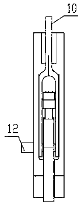
[0027] The method of hanging and taking out the rotating tumor-pushing knife suitable for channel-shaped rails. Before pushing the tumor, first place the top knife 1 on the top of the channel-shaped steel rail, and the left waist knife 2 and the right waist knife 3 are respectively wound around the first pin shaft 5 , the second pin shaft 6 is screwed down, the bottom knife 4 will be screwed up through the third pin shaft 7, and then the locking mechanism 8 and the handle pin shaft 12 are used to connect each knife body into one body, so that the whole tumor pushing knife is hung on the groove On the shaped steel rail, the action of pushing the tumor knife to hang the knife is completed; after pushing the tumor, the handle pin 12 is pulled out, the locking mechanism 8 is released, the bottom knife 4 is separated from the lower part of the right waist knife 3, and the bottom knife 4 is wound around the third pin 7 Rotate away from the bottom of the grooved steel rail, the left w...
Embodiment 3
[0029] The rotary tumor-removing knife suitable for grooved rails includes a top knife 1, a left waist knife 2, a right waist knife 3 and a bottom knife 4, and the left waist knife 2 and the right waist knife 3 are respectively arranged on the left and right sides of the top knife 1, The bottom knife 4 is located below the top knife 1, and it is characterized in that: the two ends of the top knife 1 are provided with mounting holes, the left waist knife 2 is hinged with the top knife 1 through the first pin 5, and the right waist knife 3 is connected through the second The pin shaft 6 is hinged with the top knife 1, the first pin shaft 5 passes through the mounting hole at the left end of the top knife 1, the second pin shaft 6 passes through the mounting hole at the right end of the top knife 1, and the left waist knife 2 and the bottom knife 4 A locking mechanism 8 is provided between the right waist knife 3 and the bottom knife 4 through the third pin shaft 7 being hinged. ...
PUM
 Abstract
Description
Claims
Application Information
 - R&D Engineer
- R&D Manager
- IP Professional
- Industry Leading Data Capabilities
- Powerful AI technology
- Patent DNA Extraction
Browse by: Latest US Patents, China's latest patents, Technical Efficacy Thesaurus, Application Domain, Technology Topic, Popular Technical Reports.
© 2024 PatSnap. All rights reserved.Legal|Privacy policy|Modern Slavery Act Transparency Statement|Sitemap|About US| Contact US: help@patsnap.com