
Electric machine tool

A technology of electric tools and batteries, which is applied in the direction of manufacturing tools and portable motorized devices, can solve problems such as adverse economic effects, and achieve the effects of improving service life, small self-heating, and small load

Active Publication Date: 2011-06-01
ROBERT BOSCH GMBH
View PDF13 Cites 17 Cited by
  • Summary
  • Abstract
  • Description
  • Claims
  • Application Information

AI Technical Summary

Problems solved by technology

Therefore, such a large Li-ion battery pack has a detrimental effect on economics

Method used


Image

  • Electric machine tool
  • Electric machine tool

Examples


Embodiment Construction

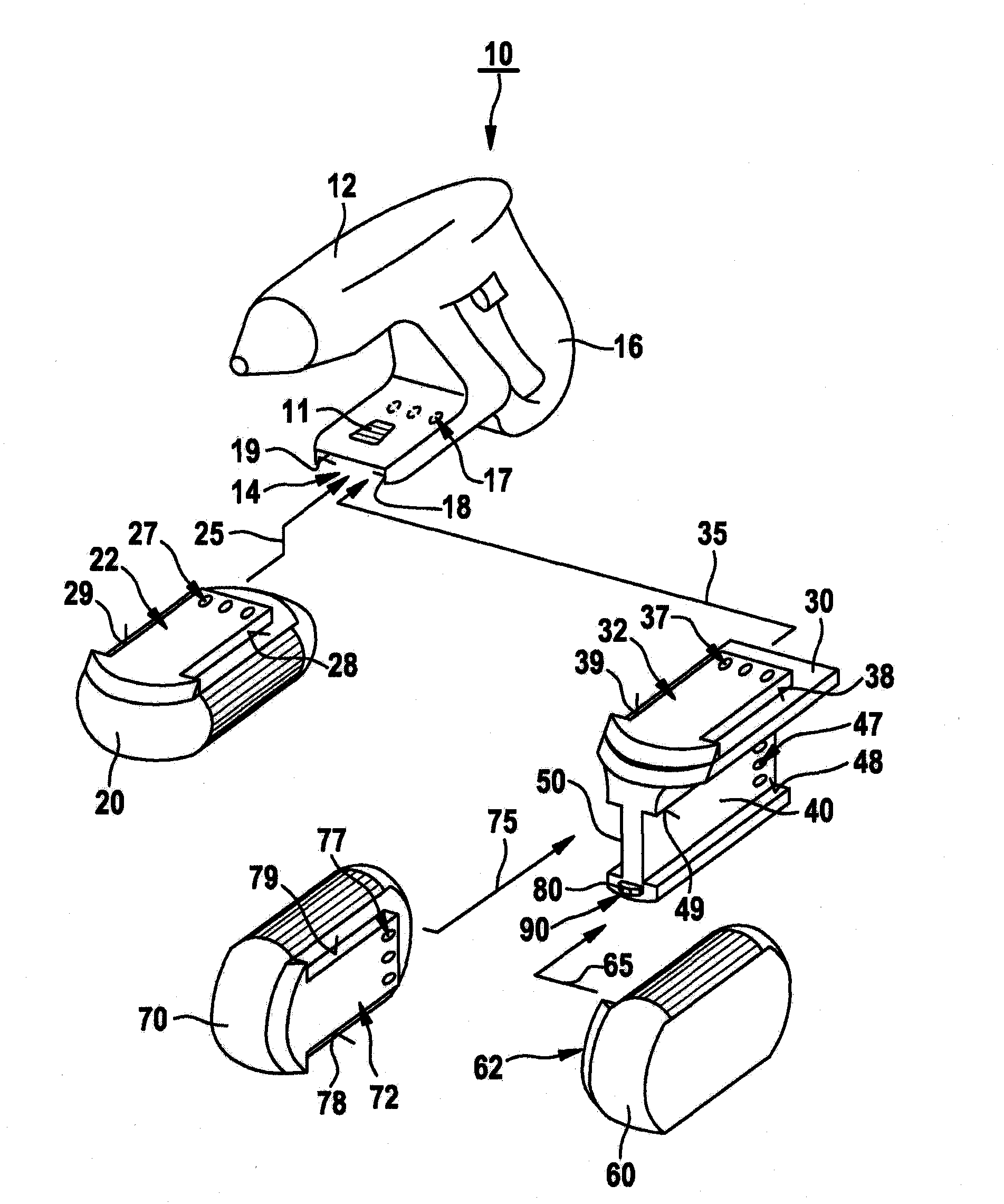
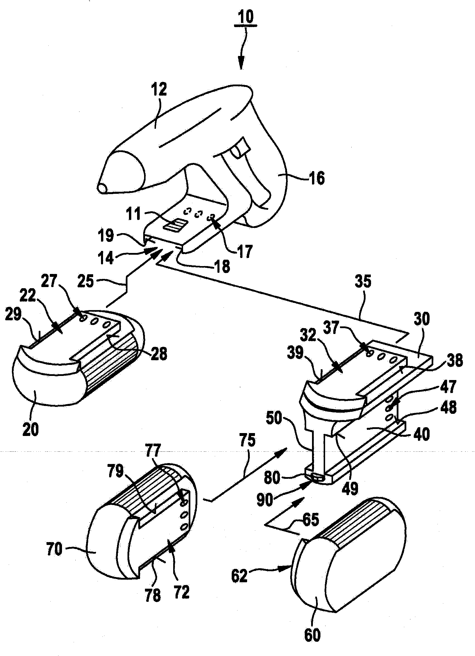
[0023] figure 1 An electric power tool 10 is shown with a housing 12 on which a handle 16 and a connection 14 are provided. Electric power tool 10 can be mechanically and electrically connected via interface 14 to battery pack 20 independently of the mains supply. exist figure 1 Among them, the electric power tool 10 is designed as a cordless drill, for example. However, it should be pointed out that the invention is not restricted to cordless drills, but rather can be applied to different electric power tools driven by batteries, such as drill hammers, angle grinders or larger, especially non-hand-held Power tools, such as lawn mowers.

[0024] The battery pack 20 has a connection interface 22 with guide or locking elements 28 , 29 for guiding or locking the battery pack 20 in the interface 14 of the electric power tool 10 , which has corresponding guide rails or docking points. Detent elements 18 , 19 cooperate with guide or detent elements 28 , 29 in order to establish ...


PUM


Abstract

In an electric machine tool having an interface (14) via which the electric machine tool can be mechanically and electrically connected to a battery pack (20), a coupling apparatus (30) is provided, which can be mechanically and electrically connected to the electric machine tool via the interface (14), wherein the coupling apparatus (30) has at least one first battery interface (40) for connection to a first battery pack (60) and at least one second battery interface (50) for connection to a second battery pack (70).

Description

technical field [0001] The invention relates to an electric power tool comprising an interface via which the electric power tool can be mechanically and electrically connected to a battery pack. Background technique [0002] Usually, the manufacturer provides different battery packs of various sizes and / or rated voltages for such electric power tools, wherein each battery pack is assigned to a specific type based on its size, rated voltage and / or power Electric machine tools. Various battery cells are also commonly available, such as nickel cadmium (NiCd), nickel metal hydride (NiMh) and lithium ion (Li-Ion). Li-ion battery packs are widely used based on their high power density. The rated voltage and capacity of the individual battery packs used or available generally determine the power and operating time of the electric power tool. [0003] A disadvantage of the prior art is that electric power tools such as large angle grinders or chainsaws, such as large angle grinde...

Claims


Application Information

Patent Timeline
IPC IPC(8): B25F5/02
CPCB25F5/02
Inventor W·马蒂亚斯R·格劳宁
Owner ROBERT BOSCH GMBH
Learn More