Double-aerated aerobic bidirectional two-way sludge backflow high-efficiency reactor with two sludge filter areas

A technology for returning sludge and sludge filtration, applied in water/sludge/sewage treatment, chemical instruments and methods, multi-stage water/sewage treatment, etc., can solve the problem of large amount of residual sludge and reduction of sludge age , Unable to guarantee the growth of sludge age and other problems, to achieve the effect of high COD removal rate

Inactive Publication Date: 2011-06-01
QINGDAO TECHNOLOGICAL UNIVERSITY
View PDF4 Cites 0 Cited by
  • Summary
  • Abstract
  • Description
  • Claims
  • Application Information

AI Technical Summary

Problems solved by technology

2. The contradiction of different sludge age reduces the treatment effect
Nitrifying bacteria, denitrifying bacteria, and COD-removing microorganisms have different sludge ages and required environments. Generally, the single-sludge system used in sewage treatment and the suspension growth of microorganisms cannot guarantee that they can obtain the best sludge age at the same time. while growing in their respective optimal environments
3. The traditional denitrification process usually adopts the pre-denitrification mode. The nitrate concentration in the effluent is the same as the nitrate concentration in the reflux digestate. The denitrification depends on the anaerobic environment to offset the load capacity of the reactor.
4. Large amount of residual sludge

Method used


Image

  • Double-aerated aerobic bidirectional two-way sludge backflow high-efficiency reactor with two sludge filter areas
  • Double-aerated aerobic bidirectional two-way sludge backflow high-efficiency reactor with two sludge filter areas
  • Double-aerated aerobic bidirectional two-way sludge backflow high-efficiency reactor with two sludge filter areas

Examples


Embodiment Construction

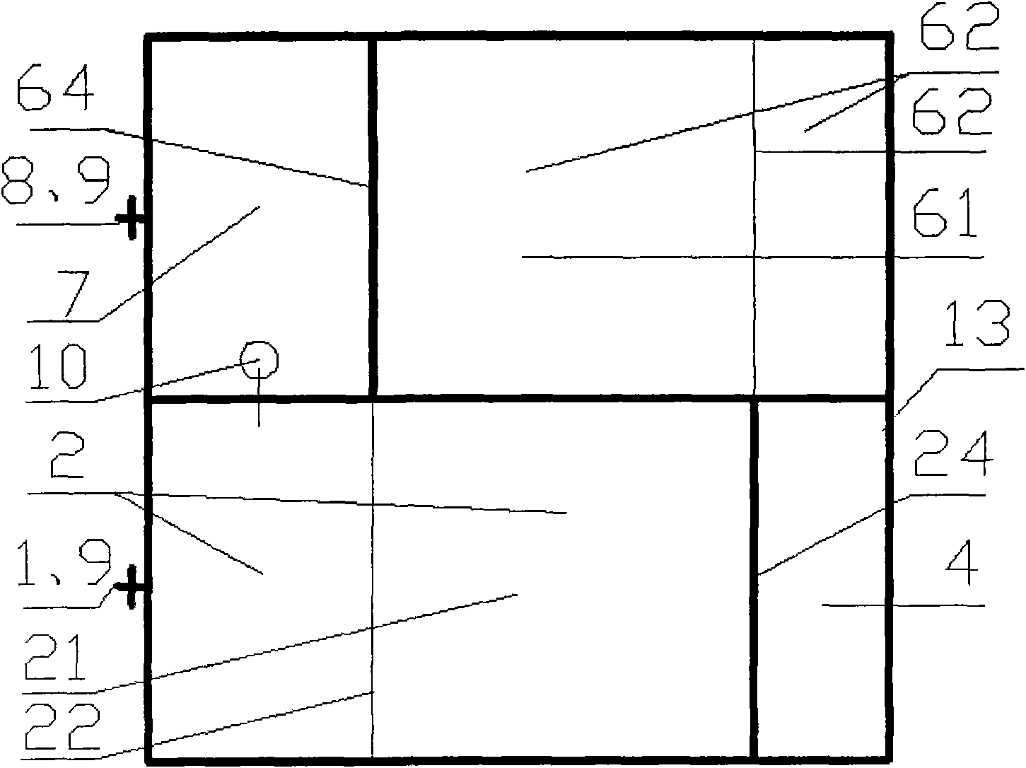
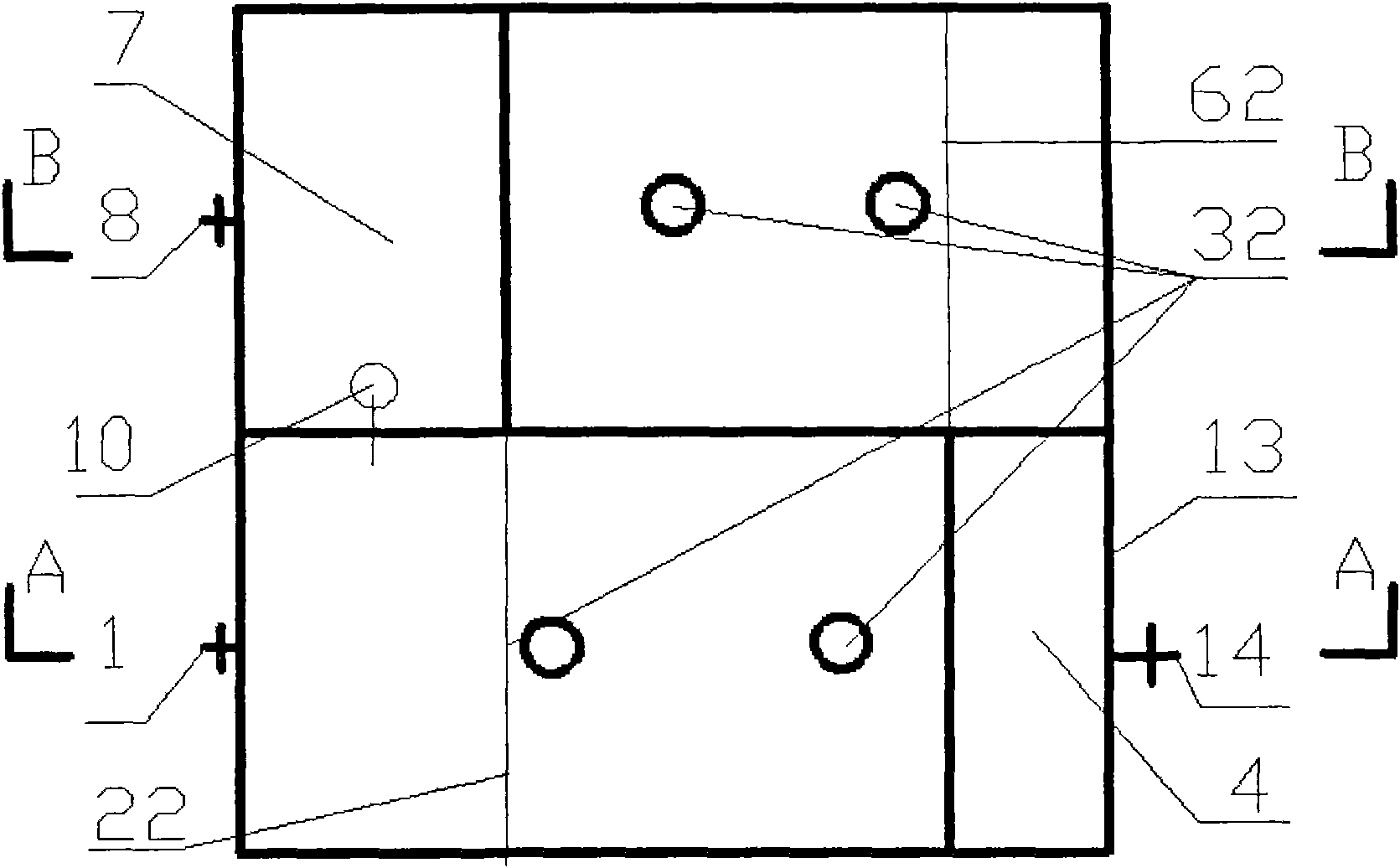
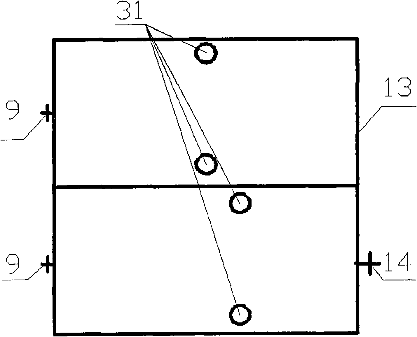
[0014]The high-efficiency reactor of double aerated aerobic two-way return sludge double sludge filtration zone of the present invention, it has tank body 13, is divided into two compartments in the tank body 13, is respectively provided with the first aeration zone 2, the first The sludge filter zone 4, the second aeration zone 6 and the second sludge filter zone 7 are provided with a water inlet pipe 1 on one side of the tank body 13, and the water inlet pipe 1 enters the first aeration zone 2, and the first aeration zone The partition plate 22 of the zone is connected with the side wall of the pool body 13 and the first longitudinal partition 24, and the first aeration zone 2 is divided into the aeration zone 21 above the first aeration zone by the partition plate 22 of the first aeration zone. And the aeration zone 23 below the first aeration zone, the dividing plate 22 of the first aeration zone has a gap on the water inlet side of the pool body 13 and the corresponding po...


PUM


Abstract

The invention discloses a double-aerated aerobic bidirectional two-way sludge backflow high-efficiency reactor with two sludge filter areas. The high-efficiency reactor comprises a tank body which are separated into two areas; a first aeration area and a first sludge filter area, and a second aeration area and a second sludge filter area are respectively formed in the two areas; a lower aerator is arranged on the lower wall of the tank body; a division plate of the first aeration area in the tank body is provided with an upper aerator; the first sludge filter area and a lower aeration area of the first aeration area are separated by a first longitudinal division plate; a gap between the first longitudinal division plate and the lower part of the tank body forms a first sludge backflow gap, so that the first sludge filter area is communicated with the lower aeration area of the first aeration area; the second aeration area is communicated with the first sludge filter area through overflow holes of a division plate of the tank body; and a division plate of the second aeration area is arranged on the wall of the tank body and a second longitudinal division plate, and a gap between the second longitudinal division plate and a bottom plate of the tank body forms a second sludge backflow gap, so that the second sludge filter area is communicated with the lower aeration area of the second aeration area.

Description

technical field [0001] The patent of the invention relates to aerobic treatment equipment with low sludge yield, high COD degradation and high nitrogen removal, which has the characteristics of high sludge concentration, high organic matter removal rate, high nitrogen removal efficiency and high load. After the air zone and two filter mud layer zones, the water is discharged, specifically, it is a high-efficiency reactor with double aerated aerobic two-way return sludge and double sludge filter zones. Background technique [0002] The eutrophication of water body caused by excessive nitrogen discharge is one of the most concerned environmental problems at present. Ammonia nitrogen (total nitrogen) has become the total control index in the special plan for water pollution prevention and control of key river basins and sea areas determined by the country. The first-level standard in my country's latest sewage discharge standard (GB18917-2002) requires that the effluent ammonia...

Claims


Application Information

Patent Timeline
Patent Type & Authority Applications(China)
IPC IPC(8): C02F9/14
Inventor 管锡珺
Owner QINGDAO TECHNOLOGICAL UNIVERSITY
Why Eureka
Try Eureka