
Underwater mechanical bionic flapping wing thruster

A technology of underwater machinery and thrusters, which is applied in the field of underwater mechanical bionic flapping wing propellers, can solve problems such as complex structures, and achieve the effects of high energy utilization, wide application prospects, and simple and reliable structures

Inactive Publication Date: 2011-06-01
NORTHWESTERN POLYTECHNICAL UNIV
View PDF1 Cites 18 Cited by
  • Summary
  • Abstract
  • Description
  • Claims
  • Application Information

AI Technical Summary

Problems solved by technology

This kind of device has a complex structure and requires precise control, so it must be equipped with a complex single-chip microcomputer control system

Method used


Image

  • Underwater mechanical bionic flapping wing thruster
  • Underwater mechanical bionic flapping wing thruster
  • Underwater mechanical bionic flapping wing thruster

Examples


Embodiment Construction

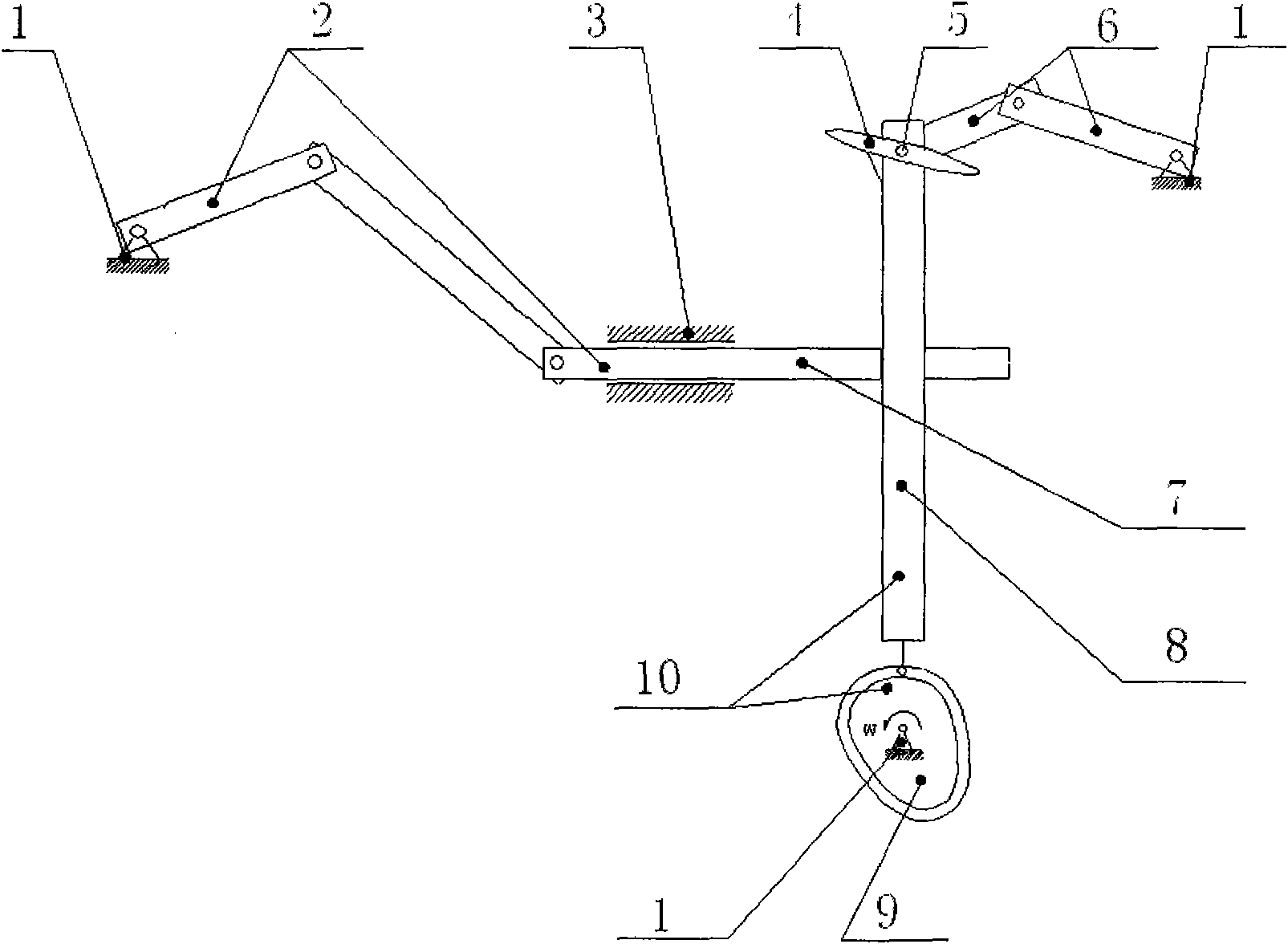
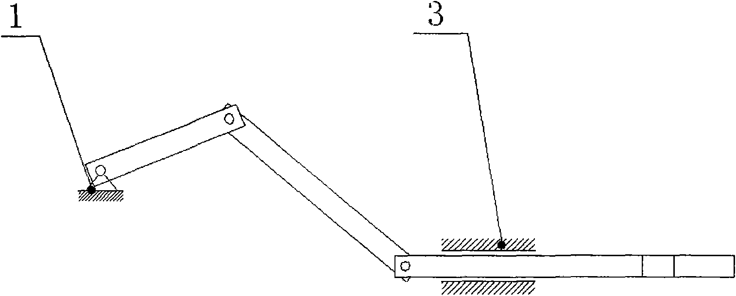
[0021] Depend on figure 1 and figure 2 It can be seen that the underwater mechanical bionic flapping wing propeller of the present invention is mainly composed of four parts: the offset crank slider mechanism 2, the cam push rod mechanism 10, the hinge mechanism 6 and the bionic flapping wing 4, and the offset crank slider mechanism 2 is composed of The fixed end 1 is used for driving, and the motor used for driving is a deceleration DC motor 11 . The decelerating DC motor 11 drives the connecting rod to rotate, thereby driving the horizontal slider 7 to move left and right in the horizontal guide rail 3 . The connecting rods are all made of 2Cr13 stainless steel, the base is made of 45# steel, and other parts are made of standard parts.

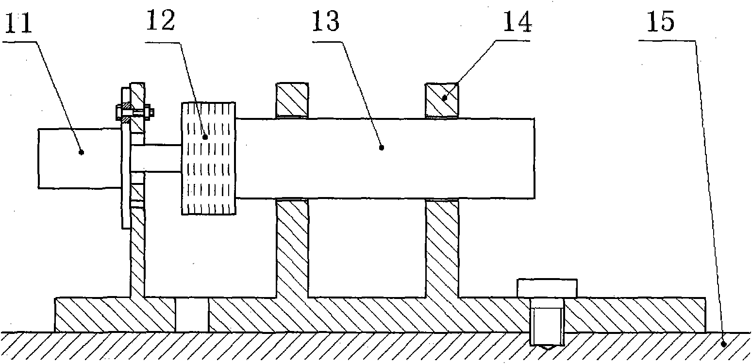
[0022] Such as image 3 As shown, the geared DC motor 11 is fixed on the motor mounting frame 14 by four M4 screws, and the motor mounting frame 14 is connected to the base 15 by four M8 screws. The motor shaft is connected with the out...


PUM


Abstract

The invention discloses an underwater mechanical bionic flapping wing thruster which comprises the following five parts: a horizontal movement mechanism, a vertical movement mechanism, a tilting movement mechanism, a bionic flapping wing and a fixed base plate. A mechanical motion separating method is used in the thruster, for imitating the flapping wing three-dimensional motion by using a simple mechanical transmission mechanism from the perspective of Kinematics. The whole motion process of the mechanism is as follows: an offset crank block mechanism is driven to move by a motor so as to drive a horizontal slide block to move left and right in a horizontal slide block motion guide rail; meanwhile, a cam push rod mechanism is driven by the motor so as to drive a vertical slide block to move vertically relative to the horizontal slide block; the two motions are superposed for realizing the fitting of the tail motion locus of the flapping wing; and at the same time, the tilting moving mechanism is driven to move so as to realize the tilting motion of the flapping wing. The underwater mechanical bionic flapping wing thruster has the characteristics of simple and reliable structure, capability of generating a stable periodic propelling force, high energy utilization rate and wide market development space.

Description

technical field [0001] The invention relates to the technical field of propulsion devices for underwater vehicles, in particular to an underwater mechanical bionic flapping wing propeller. Background technique [0002] As a kind of underwater unmanned intelligent mobile platform, the driving device of underwater vehicle mostly adopts propeller propulsion device. Especially in areas with complex seabed topography and undercurrents, waves, and swells, the requirements for the maneuverability of underwater vehicles are relatively high. In order to complete the measurement of some parameters of the ocean, the investigation of seabed information, and the fixed-point investigation tasks, it is required that the underwater vehicle should have good maneuverability and stability under low-speed conditions. It is difficult to meet this demand by propeller propulsion and maneuvering control with fin rudders. [0003] In recent years, in order to improve the maneuverability of underwa...

Claims


Application Information

Patent Timeline
IPC IPC(8): B63H1/36
Inventor 宋保维胡海豹潘光吴文辉刘占一
Owner NORTHWESTERN POLYTECHNICAL UNIV
Learn More