
Bidirectional hot-pressing high-temperature oscillation sintering furnace and working method thereof

A working method and technology of sintering furnace, which are applied in the field of sintering furnace to achieve the effects of improving product performance, high pressure and uniform force

Inactive Publication Date: 2011-05-25
邓湘凌
View PDF7 Cites 25 Cited by
  • Summary
  • Abstract
  • Description
  • Claims
  • Application Information

AI Technical Summary

Problems solved by technology

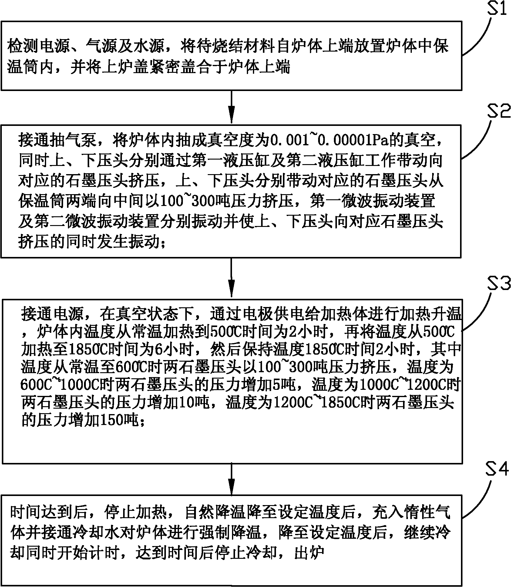
[0004] Another object of the present invention is to provide a working method of a two-way hot-pressing high-temperature oscillating sintering furnace, which solves the problem of uniform force by means of the upper and lower pressing heads while applying vibration, which has high reliability and is conducive to large batches Production

Method used


Image

  • Bidirectional hot-pressing high-temperature oscillation sintering furnace and working method thereof
  • Bidirectional hot-pressing high-temperature oscillation sintering furnace and working method thereof
  • Bidirectional hot-pressing high-temperature oscillation sintering furnace and working method thereof

Examples


Embodiment Construction

[0031] In order to further illustrate the technical means adopted by the present invention and its effects, the following describes in detail in conjunction with preferred embodiments of the present invention and accompanying drawings.

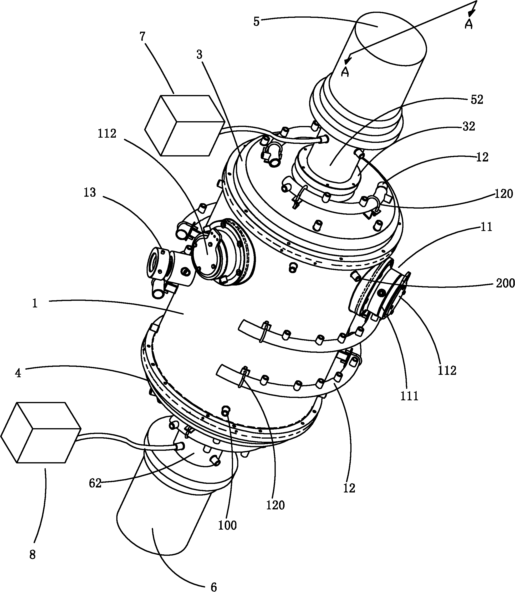
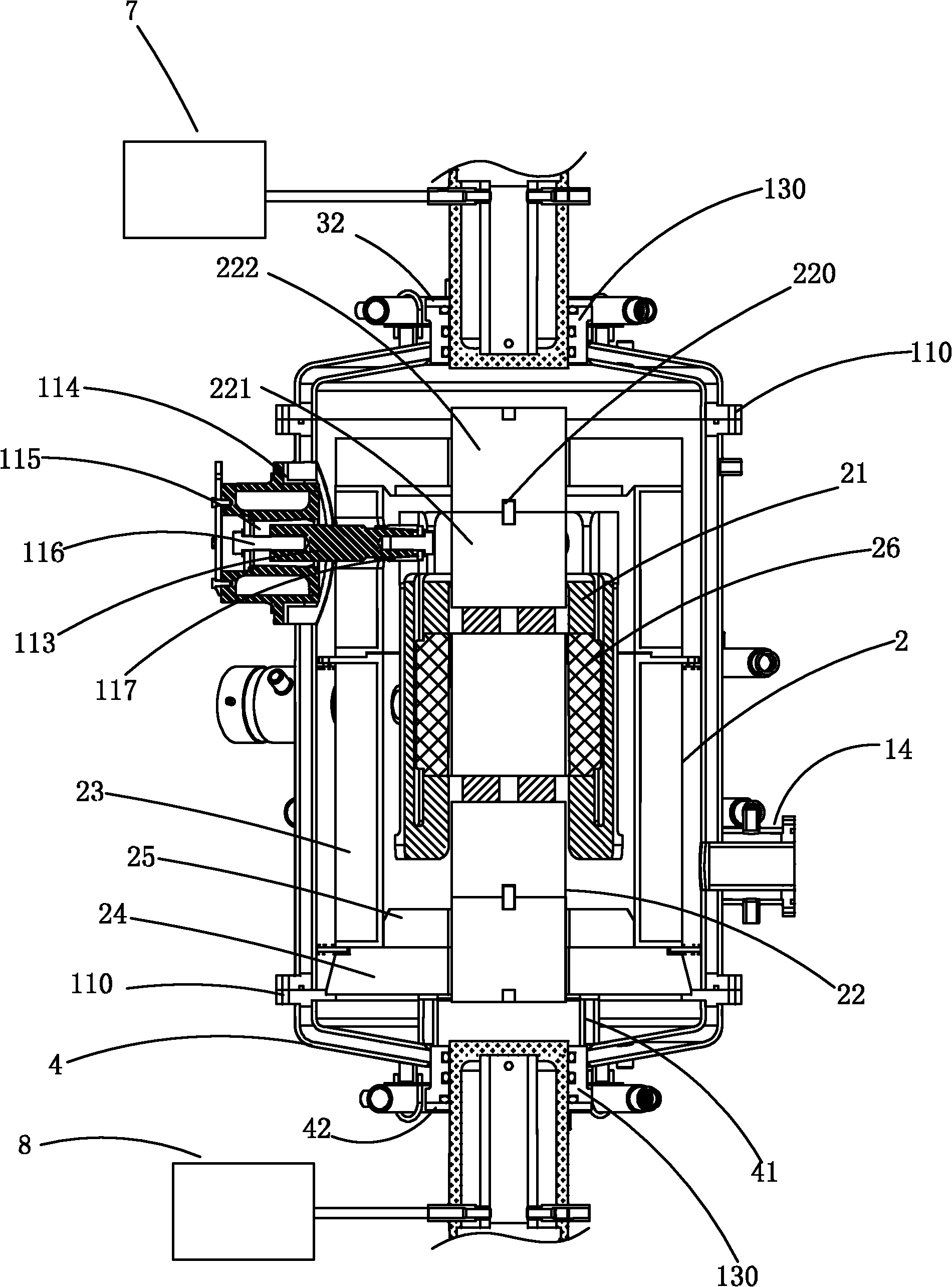
[0032] Such as Figure 1-2 As shown, the two-way hot-pressed high-temperature oscillating sintering furnace of the present invention includes: a first hydraulic cylinder 5 with a first movable rod, a second hydraulic cylinder 6 with a second movable rod, a furnace body 1, and a furnace body 1 The inner heat preservation tube 2, the upper furnace cover 3 and the lower furnace cover 4 which are respectively sealed and covered by flanges on the upper and lower ends of the furnace body 1, are integrally extended by the first movable rod of the first hydraulic cylinder 5 and installed on the upper furnace cover. 3, the lower pressing head 62 integrally extended by the second movable rod of the second hydraulic cylinder 6 and installed on the lower ...


PUM


Abstract

The invention discloses a bidirectional hot-pressing high-temperature oscillation sintering furnace and a working method thereof. The sintering furnace provided by the invention comprises a first hydraulic cylinder, a second hydraulic cylinder, a furnace body, a thermal-insulation barrel, an upper furnace cover, a lower furnace cover, an upper pressure head, a lower pressure head, a first microwave rapping device and a second microwave rapping device, wherein the first hydraulic cylinder is provided with a first moving bar; the second hydraulic cylinder is provided with a second moving bar; the thermal-insulation barrel is arranged in the furnace body; the upper furnace cover and the lower furnace cover are respectively covered on the upper end and the lower end of the furnace body in a sealing mode by a flange plate; the upper pressure head integrally extends from the first moving bar of the first hydraulic cylinder and is arranged on the upper furnace cover; the lower pressure head integrally extends from the second moving bar of the second hydraulic cylinder and is arranged on the lower furnace cover; the first microwave rapping device and the second microwave rapping device are respectively connected with the upper pressure head and the lower pressure head; the furnace body is provided with a plurality of electrodes and a plurality of water pipes fixed on the furnace body via drivepipes; a gap is formed between the thermal-insulation barrel and the inner surface of the furnace body; a heating body and two graphite pressure heads are arranged in the thermal-insulation barrel, wherein two graphite pressure heads are oppositely arranged up and down by corresponding to the upper pressure head and the lower pressure head; and the plurality of electrodes respectively andsuccessively pass through electrode through holes on the furnace body and the thermal-insulation barrel to enter into the furnace body, and are connected with the heating body.

Description

technical field [0001] The invention relates to a sintering furnace, in particular to a two-way hot-pressing high-temperature oscillating sintering furnace and its working method. Background technique [0002] The sintering furnace heats and sinters metals, ceramics and some refractory metal intermediate compound powders in a vacuum and protective atmosphere to obtain dense materials with a certain density and certain mechanical properties. Sintering furnaces mainly include vacuum hot pressing sintering furnaces and discharge plasma sintering furnaces. Among them, the vacuum hot pressing sintering furnace is a combination of vacuum, hot pressing and high temperature sintering, and is widely used in the sintering and molding of various anti-oxidation materials in the powder metallurgy industry and vacuum diffusion welding field. Preparation of the powder under pressure can increase the density of the powder and reduce various voids, especially for the formation of an excelle...

Claims


Application Information

Patent Timeline
IPC IPC(8): F27B5/05F27B5/06F27B5/14
Inventor 邓湘凌
Owner 邓湘凌
Learn More