
Teletransmission-based embedded fiber bragg grating monitoring system

A fiber grating and monitoring system technology, applied in the signal transmission system, using optical devices to transmit sensing components, instruments, etc., can solve the problems of not directly giving the physical quantity to be measured, not realizing automatic collection and remote data transmission, etc., to achieve Real-time display, reliable operation, and intuitive results

Inactive Publication Date: 2011-05-18
CENT FOR HYDROGEOLOGY & ENVIRONMENTAL GEOLOGY CGS
View PDF2 Cites 12 Cited by
  • Summary
  • Abstract
  • Description
  • Claims
  • Application Information

AI Technical Summary

Problems solved by technology

[0006] At present, many universities and companies have successively developed FBG monitoring and demodulating instruments, but most of them only demodulate the center wavelength of FBG, and do not directly give the corresponding information on the physical quantity to be measured. Relevant software or artificial Calculate the physical quantity to be measured
At the same time, in practical applications, the functions of automatic acquisition and remote data transmission under unattended conditions have not been realized, which limits the application of fiber grating demodulators in engineering

Method used


Image

  • Teletransmission-based embedded fiber bragg grating monitoring system
  • Teletransmission-based embedded fiber bragg grating monitoring system
  • Teletransmission-based embedded fiber bragg grating monitoring system

Examples


Embodiment Construction

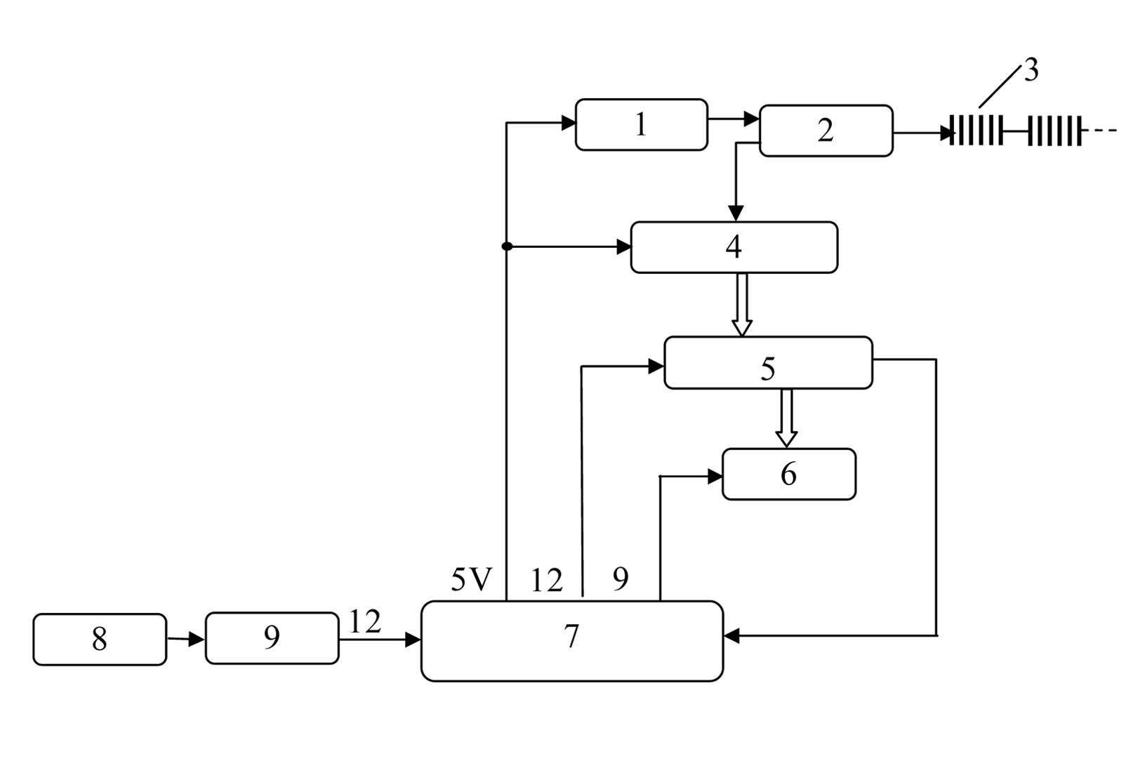
[0032] refer to figure 1 In the embodiment shown, the embedded fiber grating monitoring system based on remote transmission of the present invention includes: broadband light source 1, optical circulator 2, fiber grating sensing array 3, wavelength demodulation module 4, central control unit 5, data transmission Module 6, power control module 7, solar panel 8 and storage battery 9. The output end of the broadband light source 1 is connected to the input port of the optical circulator 2, and the light scanning output from the output port of the optical circulator 2 enters the fiber grating sensing array 3, and the reflected light of the fiber grating array 3 enters the wavelength through the reflection port of the optical circulator 2. The demodulation module 4, the wavelength demodulation module 4 demodulates the optical signal into a wavelength electrical signal, the central control unit collects these wavelength electrical signals through the fiber grating data processing so...


PUM


Abstract

The invention relates to a teletransmission-based embedded fiber bragg grating monitoring system. The system comprises a broadband light source, an optical circulator, a fiber bragg grating sensor array, a wavelength demodulation module, a central control unit, a data transmission module and a power supply control module. The broadband light produced by the broadband light source enters an input port of the optical circulator and then enters the fiber bragg grating sensor array through an output port of the optical circulator; an optical signal reflected by a grating array is fed into the wavelength demodulation module, and the wavelength demodulation module demodulates the optical signal into an electrical signal; the central control unit acquires and processes the signal in real time through application software for processing fiber bragg grating data, and automatically stores an original signal and calculated measured physical information, and the data transmission module transmits the information of a monitoring point to a numerical control center through a wireless public network; and the power supply control module controls the switch-on and switch-off of a relay through a singlechip, so that on-off of the power supplies of all the parts is controlled and the aim of reducing power consumption is fulfilled.

Description

technical field [0001] The invention belongs to the field of fiber grating sensor monitoring, in particular to a monitoring device with automatic collection and remote transmission for fiber grating engineering monitoring and a monitoring method using the device. Background technique [0002] Fiber Bragg grating is to make use of the photosensitive characteristics of optical fiber, irradiate the optical fiber with laser interference fringes, and write the grating of a certain working wavelength into the fiber core to make a fiber Bragg grating. Fiber Bragg grating sensing is to use the average refractive index of fiber grating and the sensitivity of grating period to external parameters, and convert the change of external parameters into the movement of its Bragg wavelength. When the temperature, strain, stress or other physical quantities to be measured around the grating change, the grating period or the refractive index of the fiber core will change accordingly, so that t...

Claims


Application Information

Patent Timeline
IPC IPC(8): G01D5/353G08C17/02
Inventor 张青孟宪玮史彦新韩永温张晓飞郝文杰曾克
Owner CENT FOR HYDROGEOLOGY & ENVIRONMENTAL GEOLOGY CGS
Learn More