
Process for manufacturing integral chassis towing beam for railway passenger vehicle

The invention relates to a railway passenger car and manufacturing process technology, which is applied in the field of the manufacturing process of the integral underframe traction beam of the railway passenger car, and can solve the problems of low assembly precision of the sleeper beam and high stress of the corrugated floor behind the sleeper, and achieve good market prospects, reliable quality and production efficiency. high effect

Active Publication Date: 2011-05-18
CRRC NANJING PUZHEN CO LTD
View PDF5 Cites 10 Cited by
  • Summary
  • Abstract
  • Description
  • Claims
  • Application Information

AI Technical Summary

Problems solved by technology

[0011] The technical problem to be solved by the present invention is to overcome the disadvantages of low assembling accuracy of the corrugated floor of the existing bulk assembly structure and excessively high stress of the corrugated floor behind the bolster, and provide a manufacturing process for the traction beam of the integrated underframe of a railway passenger car, which has high processing accuracy and Change the transmission path of the coupler force to solve the problem of excessive stress on the corrugated floor behind the pillow

Method used


Image

  • Process for manufacturing integral chassis towing beam for railway passenger vehicle
  • Process for manufacturing integral chassis towing beam for railway passenger vehicle
  • Process for manufacturing integral chassis towing beam for railway passenger vehicle

Examples


Embodiment Construction

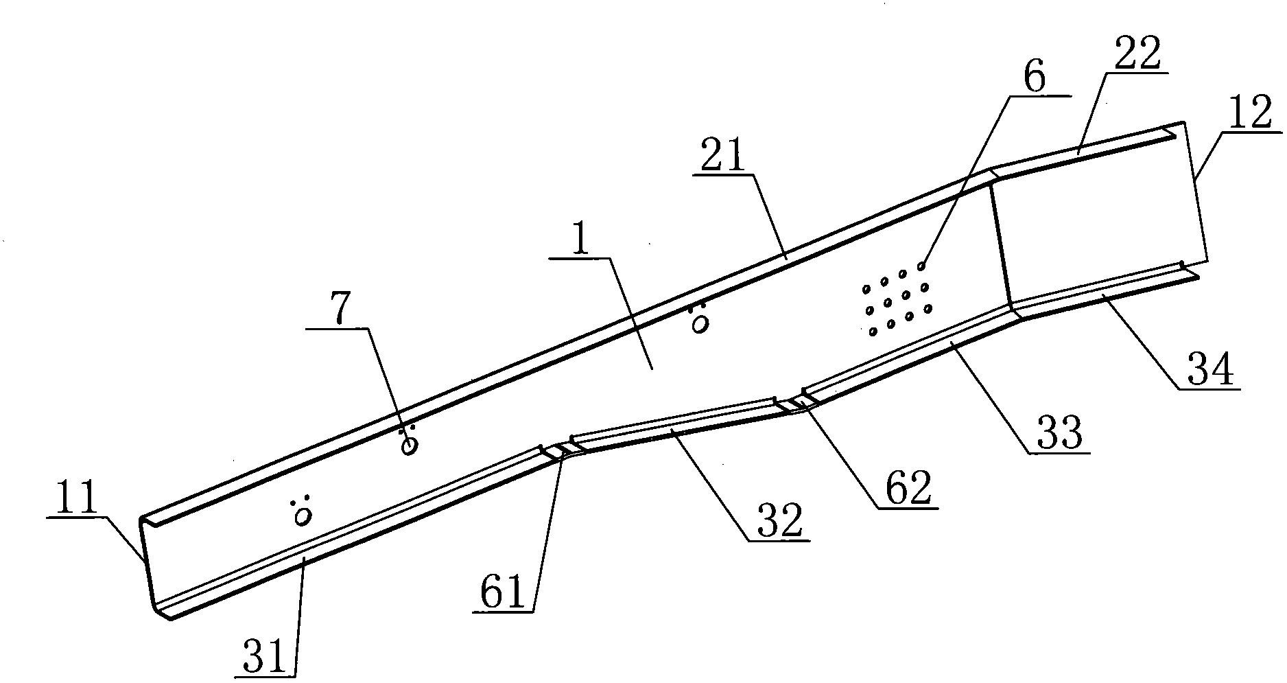
[0029] Such as Figure 1-3 As shown, it is the expanded view and structural schematic diagram of the draw beam of this embodiment.

[0030] The manufacturing process of the traction beam of the integrated underframe of the railway passenger car in this embodiment specifically includes the following steps:

[0031] The first step is steel plate shot peening pretreatment, spraying zinc silicate pre-coating primer on the steel plate;

[0032] The second step, cutting and blanking - cutting and blanking by laser cutting machine (or water jetting machine), the blanking parts after cutting include the main board 1, the corbel side 11 of the main board 1 is equal to the corbel height, and the end of the main board 1 The beam side 12 is equal to the height of the end beam, the upper end of the main board 1 along the corbel side 11 to the end beam side 12 is the first upper airfoil 21 and the second upper airfoil 22 in turn, and the lower end of the main board 1 is along the corbel si...


PUM


Abstract

The invention relates to a process for manufacturing an integral chassis towing beam for a railway passenger vehicle, comprising the following steps: preprocessing a steel plate by shot blasting; cutting and blanking, wherein each small blanked part comprises a mainboard, a first upper wing surface, a second upper wing surface, a first lower wing surface, a second lower wing surface, a third lower wing surface and a fourth lower wing surface, wherein the first upper wing surface and the second upper wing surface are distributed along the upper end of the main board, and the first lower wing surface, the second lower wing surface, the third lower wing surface and the fourth lower wing surface are distributed along the lower end of the main board; leveling the blanked parts; bending the blanked parts in sequence by steps, wherein the upper wing surfaces and the lower wing surfaces are bent towards the outside of the mainboard to be perpendicular to the mainboard; welding complementary plates between the first lower wing surface and the second lower wing surface and between the third lower wing surface and the fourth lower wing surface, and welding the joint of the first upper wing surface and the second upper wing surface and the joint of the third lower wing surface and the fourth lower wing surface; and performing ultrasonic flaw detection on welding joints, and welding the hollow welded joints. The welded joint is shortened, thus the welding deformation is reduced and less special welding tools and clamping tools are used; the whole part is integrally blanked by adopting a numerically controlled cuter, thus the pitch of holes is guaranteed; and the working efficiency is improved to a great extent, and the cost is reduced.

Description

technical field [0001] The invention relates to a manufacturing process of a traction beam of an integral underframe of a railway passenger car, and belongs to the technical field of the underframe structure of a railway passenger car. Background technique [0002] The traction beam is an important part of the bus chassis and is the main carrier of longitudinal and lateral loads, and its shape is relatively complex. The traction beam of the chassis of ordinary railway passenger cars is formed by splicing 30a channel steel 0 with material Q235B. [0003] In the existing drawing beam production process, the drawing beam is formed by splicing two processed channel steels, wherein the first channel steel cuts off a part of the lower wing surface, the second channel steel retains one side wing surface, and cuts the front end into an acute angle, specifically The steps of the process are as follows: [0004] The first step, channel steel scribing and cutting; [0005] In the se...

Claims


Application Information

Patent Timeline
IPC IPC(8): B23P15/00
Inventor 何伯庆谢秉顺丁亚萍廖冬冬张勇鲁万彪刘建军
Owner CRRC NANJING PUZHEN CO LTD
Learn More