Linear compressor with magnetic spring structure

A technology of linear compressors and magnetic springs, applied in the direction of magnetic springs, springs, springs/shock absorbers, etc., can solve the problems of reduced reliability and stability, reduced compressor performance, gas leakage, etc., and achieves compact structure and easy processing Simple, performance-enhancing effects

Inactive Publication Date: 2011-05-11
XI AN JIAOTONG UNIV
View PDF5 Cites 10 Cited by
  • Summary
  • Abstract
  • Description
  • Claims
  • Application Information

AI Technical Summary

Problems solved by technology

The natural frequency of the linear compressor is not only related to the mass of the moving components and the stiffness of the spring, but also affected by the exhaust pressure and the stroke of the piston. The stiffness coefficient of the mechanical spring is constant in a certain period of time, and as time increases, its stiffness The coefficient will become smaller. When the operating conditions of the compressor change, the natural frequency of the system will change, making the operating frequency and the natural frequency mismatch, reducing the performance of the compressor. At the same time, the mechanical spring is under a large piston stroke. , its reliability and stability decrease
[0005] The gas spring is a resonant spring with a variable stiffness coefficient, which can be used in linear compressors, but its performance and reliability are seriously affected due to gas leakage. To improve its performance and reliability, it is necessary to increase its self-filling gas device, which will increase the complexity of the gas spring processing and manufacturing process

Method used


Image

  • Linear compressor with magnetic spring structure
  • Linear compressor with magnetic spring structure
  • Linear compressor with magnetic spring structure

Examples


Embodiment Construction

[0024] Accompanying drawing is the specific embodiment of the present invention;

[0025] Below in conjunction with accompanying drawing, content of the present invention is described in further detail:

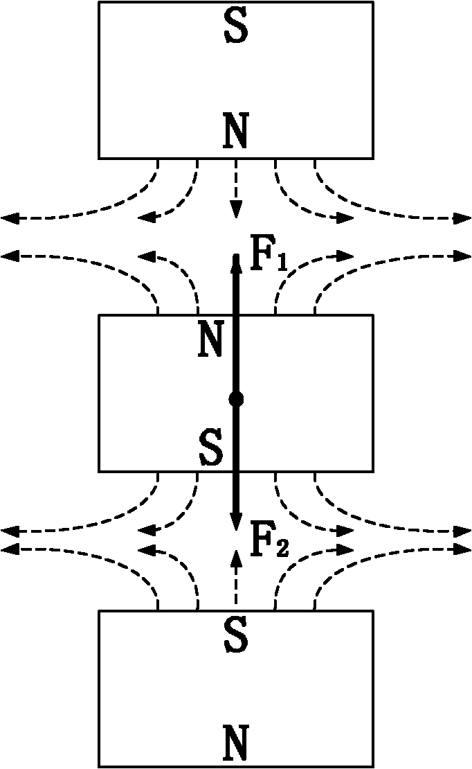
[0026] figure 1 It is a schematic diagram of a magnetic spring, which consists of three sets of permanent magnets. The upper and lower permanent magnets are in a fixed state, and the middle permanent magnet is in a free-moving state. The permanent magnets are placed in the same direction, and the moving magnet in the middle is subjected to the repulsive force F of the upper and lower fixed magnets 1 and F 2 Effect, when the resultant force is zero, the moving magnet is in a balanced state. Without considering the gravity of the moving magnet itself, the resultant force on the moving magnet is

[0027] F s ( x ) = π B r ...


PUM


Abstract

The invention relates to a magnetic spring structure and a linear compressor structure thereof, in particular relating to a linear compressor with a magnetic spring structure. The linear compressor is characterized in that a magnetic spring assembly is composed of a permanent moving magnet and a permanent stationary magnet, the permanent stationary magnet is fixed on a compressor body, and the permanent moving magnet, a piston and a motor rotor constitutes a piston motion assembly; under the action of alternating thrust of a motor, the piston motion assembly makes a reciprocating linear motion along the axial direction of the motor so as to complete a process comprising the steps of expansion, air suction, compression and air exhaust of the compressor; and meanwhile, under the action of mutual magnetic forces, the permanent moving magnet and the permanent stationary magnet are acted as energy-storage components. The linear compressor with a magnetic spring structure has the advantages that the equivalent stiffness coefficients of the permanent magnets can be changed through changing the diameters, coercive forces and remanence strengths of the permanent magnets; when the compressor is in a large piston stroke, the compressor still has high performances and reliability; and because the magnetic spring is simple in structure, the permanent moving magnet part of the magnetic spring can be inlaid on the piston, so that the structure of the linear compressor is more compact and the volume thereof is smaller.

Description

technical field [0001] The invention relates to a magnetic force spring structure and a linear compressor thereof, in particular to a linear compressor with a magnetic force spring structure. Background technique [0002] The traditional gas compressor is a reciprocating piston mechanism with a crank connecting rod mechanism. The crank connecting rod converts the rotary motion of the motor into the reciprocating linear motion of the piston. Because the piston is subjected to the lateral force, the distance between it and the cylinder wall needs to be Lubricating oil lubrication makes this traditional air compressor have disadvantages such as large volume, complex structure, high noise, oily gas, and limited application occasions. [0003] Linear compressor is a kind of power machine whose piston is directly driven by linear motor to do reciprocating linear motion. Since the gas force, electromagnetic force and frictional damping force on the piston are distributed along the ...

Claims


Application Information

Patent Timeline
IPC IPC(8): F16F6/00F04B39/00
Inventor 畅云峰张金权
Owner XI AN JIAOTONG UNIV
Why Eureka
Try Eureka