
Pneumatic tire

A technology for pneumatic tires and tires, applied to the reinforcement layer of pneumatic tires, tire parts, tire tread/tread pattern, etc., which can solve the problems of inability to obtain ground contact area, deterioration of anti-slip performance, and easy occurrence of swaying , to achieve the effect of improving anti-yaw performance, improving icy road performance and reducing reaction force

Inactive Publication Date: 2011-05-11
SUMITOMO RUBBER IND LTD
View PDF6 Cites 11 Cited by
  • Summary
  • Abstract
  • Description
  • Claims
  • Application Information

AI Technical Summary

Problems solved by technology

[0003] However, if Figure 10 As shown in (a), since the above-mentioned pneumatic tire can ensure an appropriate ground contact width w1 when the normal load n1 specified in the specifications is applied, an optimal and large ground contact area can be obtained. However, when the normal load is applied In the case of a smaller load n2, such as Figure 10 As shown in (b), since the contact width w2 is smaller than the above contact width w1, the desired contact area cannot be obtained.
[0004] In addition, in a pneumatic tire with an enlarged tread width, the tread end and a part of the wall surface tend to come into contact with the slope of the rut, etc., and the tire is shaken by an external force from the road surface, and it is easy to yaw.
Therefore, although increasing the ground contact area can improve the performance on ice, on the other hand, there is a problem of deteriorating the anti-yaw performance.

Method used


Image

  • Pneumatic tire
  • Pneumatic tire
  • Pneumatic tire

Examples


Embodiment Construction

[0026] Hereinafter, an embodiment of the present invention will be described based on the drawings.

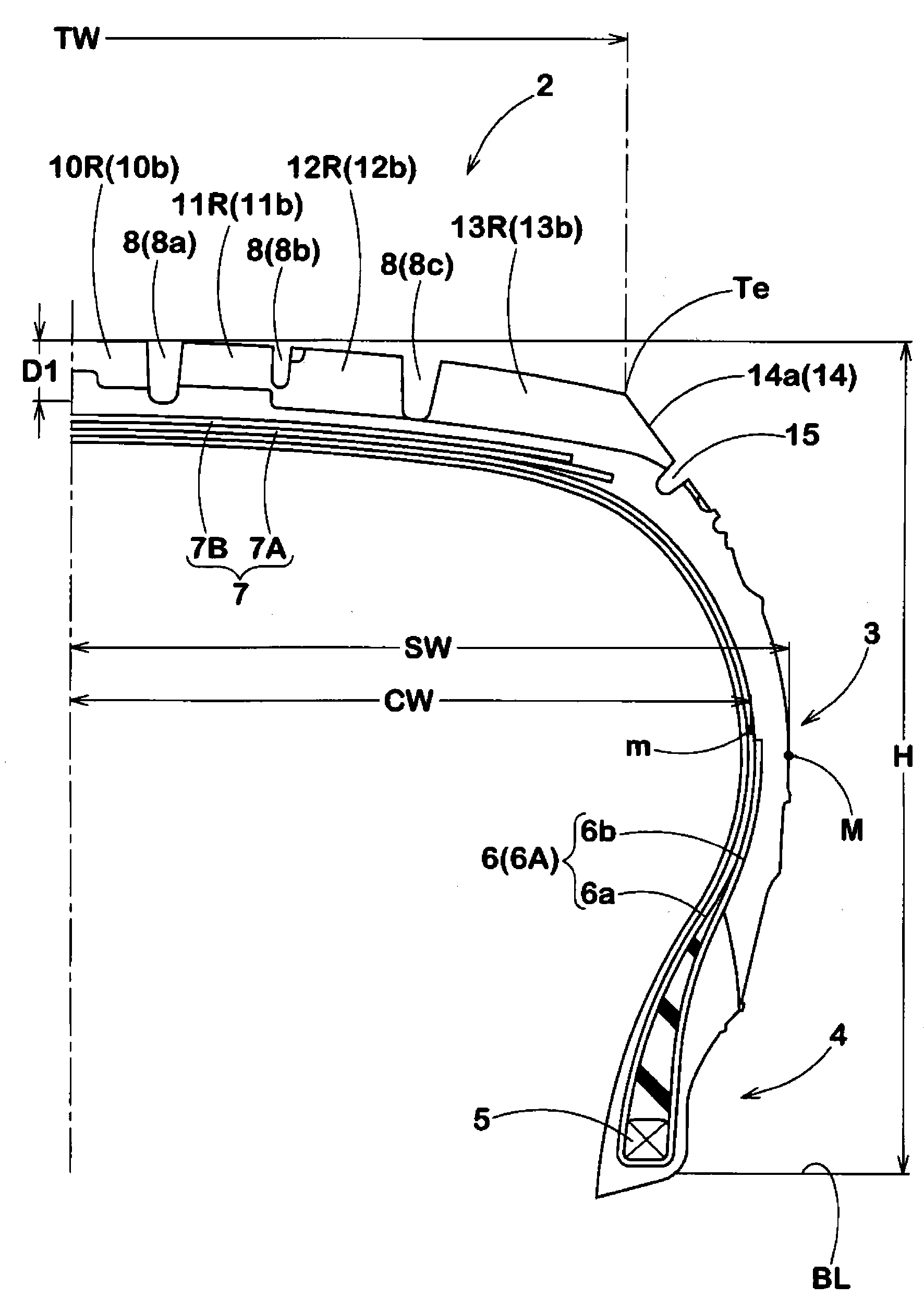
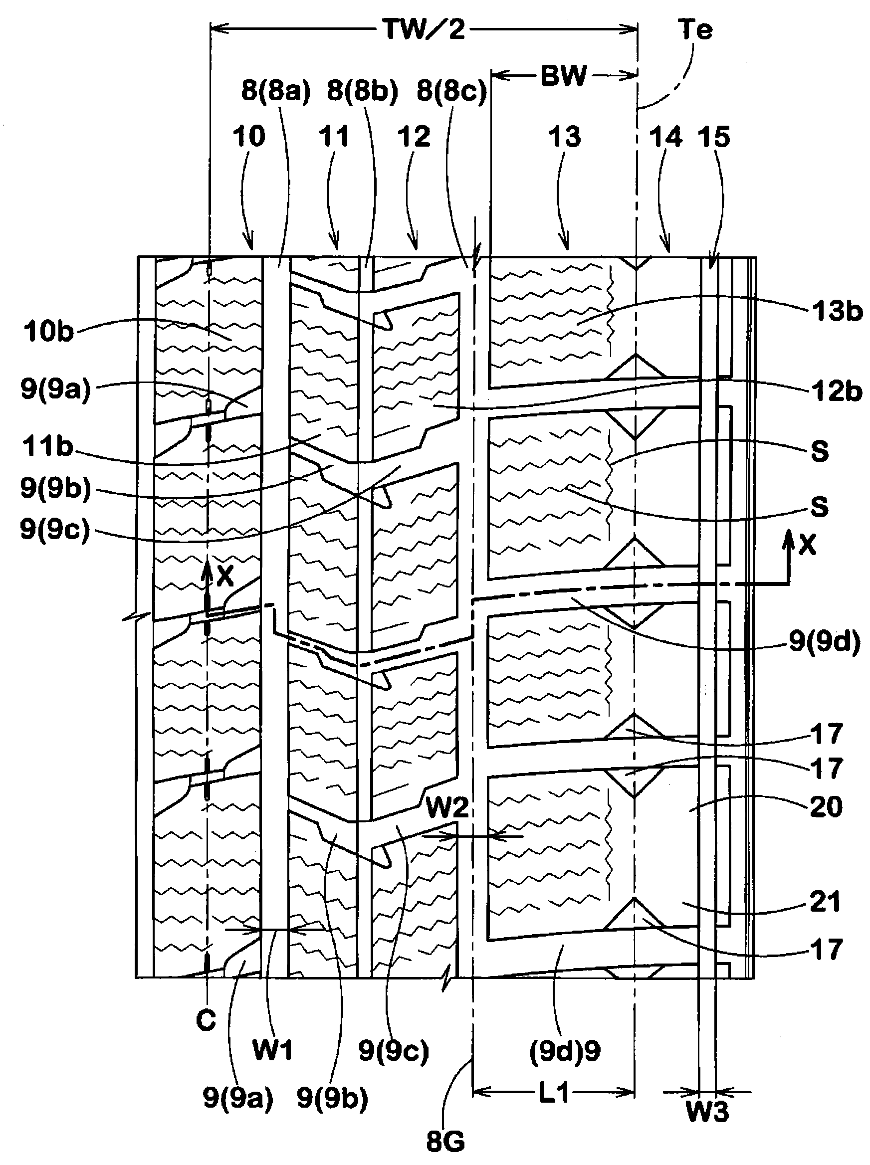
[0027] figure 1 Is a cross-sectional view showing the right half of the pneumatic tire 1 of this embodiment, figure 2 Is its expanded view. among them, figure 1 The cross-sectional view of shows a meridian section including the tire rotation axis in a normal state where it is mounted on a normal rim (not shown) and filled with normal internal pressure without load. Unless otherwise specified, the dimensions of each part of the tire are the values ​​measured in the normal state.

[0028] The above-mentioned “regular rim” refers to the rim specified for each tire in the specification system including the specifications on which the tire is based. If it is JATMA, it is “standard rim”, if it is TRA, it is “Design Rim”. ETRTO is "Measuring Rim". In addition, the above-mentioned "regular internal pressure" refers to the air pressure specified for each tire in the specification syste...


PUM


Abstract

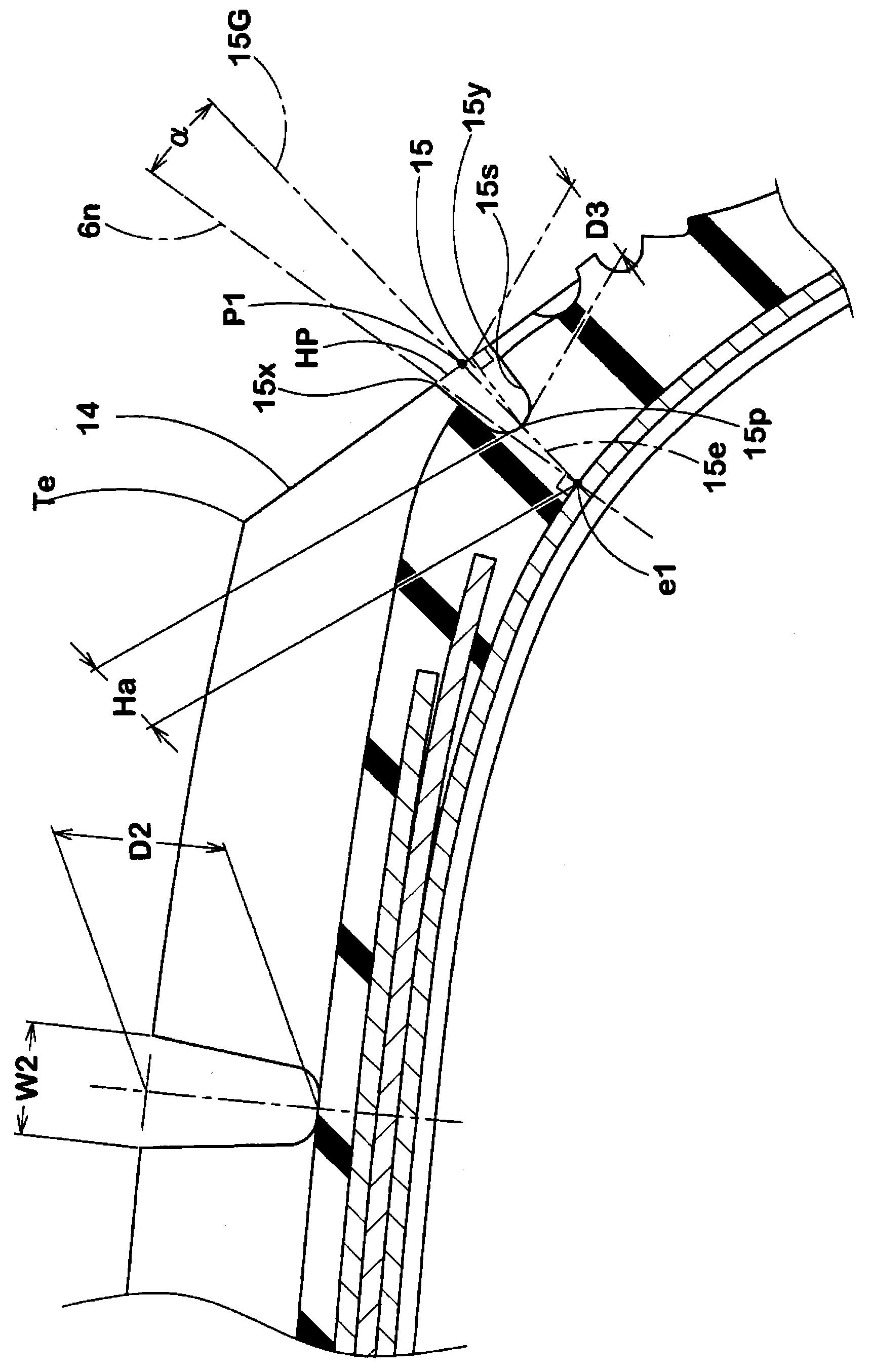
The invention provides a pneumatic tire, which symmetrically improves the on-ice performance and the driving performance of a vehicle. When the pneumatic tire is assembled to a regular rim and filled with a regular inner pressure of a normal state without load, the ratio (TW / SW) of the tread width (TW) between the tread ends (Te) to the maximum width (SW) of a tire is 0.75 to 0.95. The tire surface (14) is equipped with a continuously extending thin groove (15) along the circumferential direction of the tire. The center line (15G) of the groove (15) and the normal (6n) of the carcass are at an angle (alpha) of small than 10 degrees, wherein the normal (6n) of the carcass passes through the extension line (15e) of the center line (15G) and the point of intersection thereof with the carcass (6) is (e1). A pair of shoulder main grooves (8c) continuously extending along the circumferential direction of the tire are arranged on the outer side of the tread end (Te) of the tread portion (2). The depth (D3) of the thin groove (15) is 20% to 50 % of the depth (D2) of the shoulder main grooves (8c).

Description

Technical field [0001] The present invention relates to a pneumatic tire that can balance the performance on ice and the rutting performance. Background technique [0002] In the past, there have been proposed pneumatic tires that ensure a larger ground contact area by increasing the tread width and land ratio. Since such a pneumatic tire can obtain a large frictional force with the road surface, it can improve the running performance on icy roads. [0003] However, as Picture 10 As shown in (a), since the above-mentioned pneumatic tire can ensure an appropriate ground contact width w1 when the normal load n1 specified in accordance with the specifications is applied, it can obtain the best and larger ground contact area, but when the load is less than the normal load In the case of a smaller load n2, such as Picture 10 As shown in (b), since the ground contact width w2 is smaller than the ground contact width w1, the desired ground contact area cannot be obtained. [0004] In addi...

Claims


Application Information

Patent Timeline
Patent Type & Authority Applications(China)
IPC IPC(8): B60C9/02B60C11/117B60C11/03
Inventor 高桥伸吾
Owner SUMITOMO RUBBER IND LTD
Learn More