Detonation tube structure of multi-tube pulse detonation engine

A technology of pulse detonation and detonation tube, which is used in mechanical equipment, intermittent injection devices, etc., can solve the problems of high ignition energy and simple structure, and achieves the goal of weakening strength, maintaining synchronization, and reducing pressure back-propagation. Effect

Inactive Publication Date: 2011-05-04
NORTHWESTERN POLYTECHNICAL UNIV
View PDF3 Cites 14 Cited by
  • Summary
  • Abstract
  • Description
  • Claims
  • Application Information

AI Technical Summary

Problems solved by technology

[0004] In order to solve the problem that the existing ignition method cannot take into account the simple structure and high ignition energy, the present invention proposes a detonation tube structure for a multi-tube pulse detonation engine

Method used


Image

  • Detonation tube structure of multi-tube pulse detonation engine
  • Detonation tube structure of multi-tube pulse detonation engine

Examples


Embodiment 1

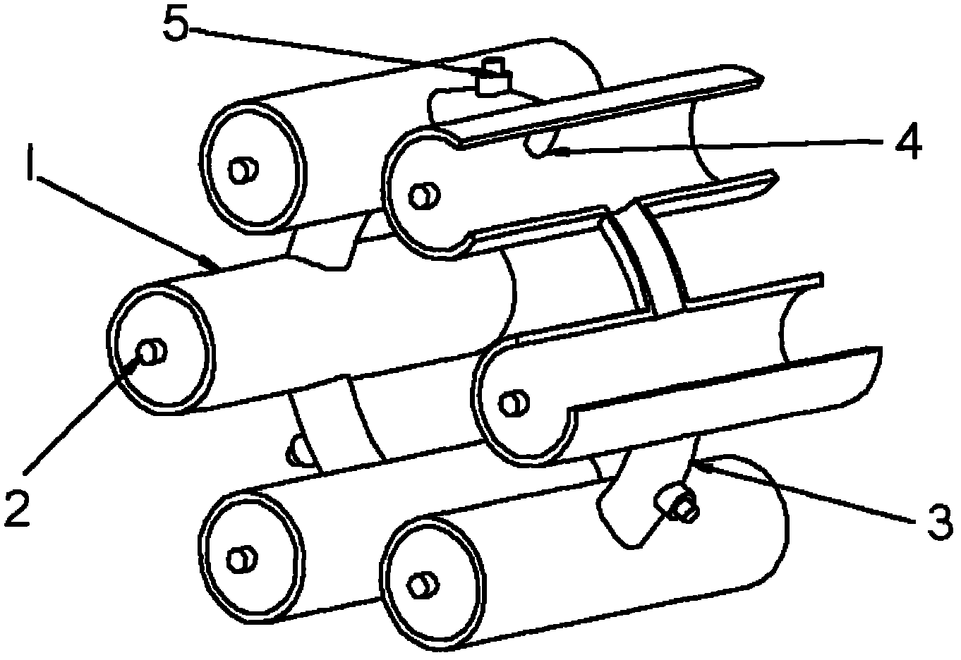
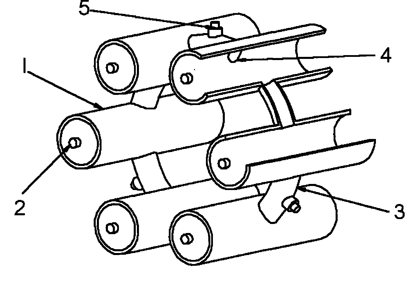
[0015] The detonation tube structure of the multi-tube pulse detonation engine in this embodiment includes 6 detonation tubes 1, the inner diameter of a single detonation tube is 50 mm, the wall thickness of the tube is 4 mm, and the total length of a single detonation tube is 1500 mm; The central axes of the shock tubes are evenly distributed along the circumferential direction, that is, the central axes of the six detonation tubes are on the same circumferential surface, the circumference diameter is 250mm, and the central angles of the central axes of the two adjacent detonation tubes are the same as 60° .

[0016] The two adjacent detonation tubes are connected through the cross-fire tube 3, each cross-fire tube 3 is arc-shaped, and the radius of the arc is the same as 125mm, and the central axis length of each cross-fire tube 3 is 72.8mm , which is 1.26 times the outer diameter of the detonation tube. The inner diameter of the cross-fire tube is 20mm, which is 0.4 times ...

Embodiment 2

[0019] The detonation tube structure of the multi-tube pulse detonation engine in this embodiment includes 6 detonation tubes 1, the inner diameter of a single detonation tube is 40mm, the tube wall thickness is 4mm, and the total length of a single detonation tube is 1500mm; The central axes of the shock tubes are evenly distributed along the circumferential direction, that is, the central axes of the six detonation tubes are on the same circumferential surface, the circumference diameter is 250mm, and the central angles of the central axes of the two adjacent detonation tubes are the same as 60° .

[0020] The two adjacent detonation tubes are connected through the cross-fire tube 3, each cross-fire tube 3 is arc-shaped, and the arc radius is the same as 125mm, and the central axis length of each cross-fire tube 3 is 82.8mm , which is 1.73 times the outer diameter of the detonation tube. The inner diameter of the cross-fire tube is 40mm, which is 1 times the inner diameter ...


PUM


Abstract

The invention provides a detonation tube structure of a multi-tube pulse detonation engine, which is characterized by comprising at least two detonation tubes, wherein the central axes of all detonation tubes are uniformly distributed along the circumferential direction; two adjacent detonation tubes along the circumferential direction are communicated through a circular arc flame crossover tube; the internal diameter ratio of the flame crossover tube to the detonation tubes is 1 / 3:1; the distance between the central axis of the flame crossover tube and the fuel nozzle of each detonation tube is 2 to 4 times the internal diameter of the detonation tube; and an igniter is arranged at the middle position of the wall of each flame crossover tube. By the detonation tube structure, the ignition energy of a single tube in the multi-tube pulse detonation engine can be improved on the premise of small energy ignition, the deflagration to detonation transition (DDT) distance of the single tube under the same ignition condition is shortened, the adverse effect of fuel gas back transmission on the air-breathing multi-tube pulse detonation engine can be reduced, and the synchronism of multi-tube work is improved.

Description

technical field [0001] The invention relates to the field of pulse detonation engines, in particular to a detonation tube structure of a multi-tube pulse detonation engine. Background technique [0002] The pulse detonation engine is a new concept propulsion device that uses high-temperature, high-pressure gas generated by intermittent detonation waves to generate thrust. The multi-tube parallel pulse detonation engine has a series of advantages such as high thermal cycle efficiency, simple structure, and wide thrust range. However, the multi-tube parallel pulse detonation engine needs to solve the problem of reliable ignition of each single tube. At present, the ignition of multi-tube pulse detonation engines generally adopts two methods: weak spark ignition and jet ignition. The former, through the optimal design of the ignition zone, forms a combustible mixed gas low-velocity zone and a mixture gas concentration suitable for ignition in the ignition zone, and realizes de...

Claims


Application Information

Patent Timeline
IPC IPC(8): F02K7/02
Inventor 范玮彭畅新袁成王玮张群严传俊
Owner NORTHWESTERN POLYTECHNICAL UNIV
Why Eureka
Try Eureka