Eureka AIR delivers breakthrough ideas for toughest innovation challenges, trusted by R&D personnel around the world.

Device for detecting qualifying diameter dimensions of shafts

A technology for detecting shafts and dimensions, applied in the direction of mechanical diameter measurement, etc., can solve the problems of increasing production costs of manufacturers, inconvenient installation, and failure to find out in time, and achieve the effect of eliminating production accidents

Active Publication Date: 2011-04-27
CHERY AUTOMOBILE CO LTD
View PDF5 Cites 8 Cited by
  • Summary
  • Abstract
  • Description
  • Claims
  • Application Information

AI Technical Summary

Problems solved by technology

[0003] 1. The main journal lathe in the previous process often breaks the tool, and it is produced automatically, so it cannot be found in time;
[0004] 2. Due to the inability to process in the previous process, the workpiece with an oversized shaft diameter directly enters the grinding machine, causing the grinding wheel of the grinding machine to collide with the workpiece in rapid feed, resulting in a safety accident
[0005] In order to avoid the above situation, manufacturers often set up special personnel between the two processes to manually load and unload parts and perform manual measurement, which is time-consuming and labor-intensive, and the work efficiency is low
However, some manufacturers add Marposs measuring instrument between two processing procedures to measure the spindle journal transported from the turning processing line to determine whether the workpiece size exceeds the standard. There are also the following problems: First, the Marposs measuring instrument is expensive, It greatly increases the production cost of the manufacturer; secondly, due to the limitation of the volume of the measuring instrument and the installation site, it is inconvenient to install

Method used


Image

  • Device for detecting qualifying diameter dimensions of shafts
  • Device for detecting qualifying diameter dimensions of shafts
  • Device for detecting qualifying diameter dimensions of shafts

Examples


Embodiment Construction

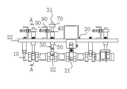
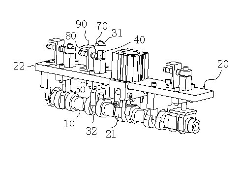
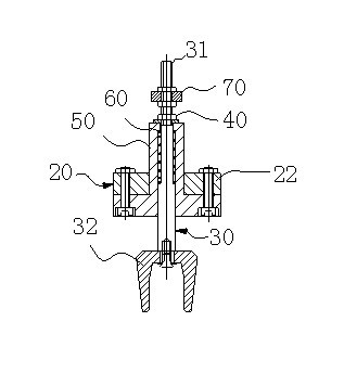
[0016] A device for detecting qualified diameters of shafts, including a positioning mechanism 20 for positioning with the measured shaft 10, the device also includes a measuring piece 30 that can move linearly, and the measuring piece 30 translates along the guide mechanism 50, the The measuring part 30 is provided with a reference part, and the axis distance from the reference part to the measured shaft 10 coincides with the standard value of the radius of the measured part of the measured part 10, and the device also includes a limit mechanism 40 for limiting the nearest position of the measuring part 30 ,like figure 1 and figure 2 shown.

[0017] As a further preferred solution of the present invention, the measuring piece 30 includes a measuring rod 31 and a clip 32 arranged at one end of the measuring rod 31, and the opening direction of the clip 32 points to one side of the component to be measured, such as Figure 1-4 As shown, the clip 32 here is similar to the bay...


PUM


Abstract

The invention belongs to the field of machining lines of shafts and in particular to a device for detecting and qualifying diameter dimensions of shafts. The device provided by the invention comprises a positioning mechanism, a measuring component and a limiting mechanism, wherein the positioning mechanism is used for being positioned with a measured shaft; the measuring component can move linearly; the measuring component moves horizontally along a guide mechanism; a reference part is arranged on the measuring component; the distance between the reference part and the shaft line of the measured shaft is matched with the standard value of the radius of the measured part of the measured shaft; and the limiting mechanism is used for limiting the nearest position of the measuring component. Because in the invention, the error correction is realized by depending on the physical measurement in a form similar to a go / no-go gauge, the device has the advantages of good stability and high error correction efficiency and can effectively avoid the occurrence of production accidents.

Description

technical field [0001] The invention belongs to the field of shaft machining lines, and in particular relates to a device for detecting qualified diameters of shafts. Background technique [0002] With the development of modern society, the performance requirements of automobiles are getting higher and higher. The engine is the heart of the automobile, and the engine camshaft is the main part of the engine valve train. Its shape and precision have a great influence on the performance of the engine. It is the engine One of the key parts, therefore, puts strict requirements on its manufacturing precision. The main process of machining is generally: milling end face drilling center hole → turning main journal and opening crotch → rough grinding main journal → hobbing, milling keyway → turning cam → rough grinding cam → surface quenching → fine grinding main journal → semi-finishing Grinding and fine grinding cams are generally transported between processes by pneumatic gripper...

Claims


Application Information

Patent Timeline
Patent Type & Authority Applications(China)
IPC IPC(8): G01B5/08
Inventor 刘思军安刚虎王二镇章华田明张久云姚国庆吴俊宁
Owner CHERY AUTOMOBILE CO LTD
Why Eureka
Eureka Blog
Learn More