
System for ultrasonically detecting defects in a pipe wall

A technology for detecting tubes and tube walls, which can be used in the analysis of solids using sonic/ultrasonic/infrasonic waves, fluids using vibration, and material analysis using sonic/ultrasonic/infrasonic waves, which can solve problems such as unreliable imaging.

Inactive Publication Date: 2011-04-13
NEDERLANDSE ORG VOOR TOEGEPAST-NATUURWETENSCHAPPELIJK ONDERZOEK (TNO)
View PDF1 Cites 10 Cited by
  • Summary
  • Abstract
  • Description
  • Claims
  • Application Information

AI Technical Summary

Problems solved by technology

Due to the considerable difference in the speed of sound between the tube wall and the fluid inside the tube, this inhomogeneity results in considerable scattering of the ultrasonic rays at unpredictable angles
This would make imaging with the system in EP 1707956 very unreliable in pipes subject to corrosion and wear

Method used


Image

  • System for ultrasonically detecting defects in a pipe wall
  • System for ultrasonically detecting defects in a pipe wall
  • System for ultrasonically detecting defects in a pipe wall

Examples


Embodiment Construction

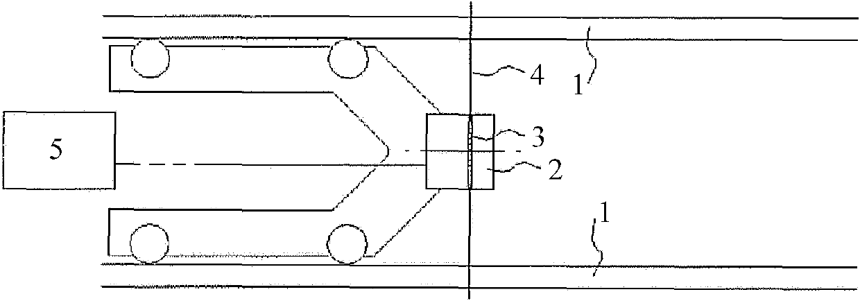
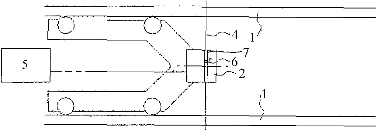
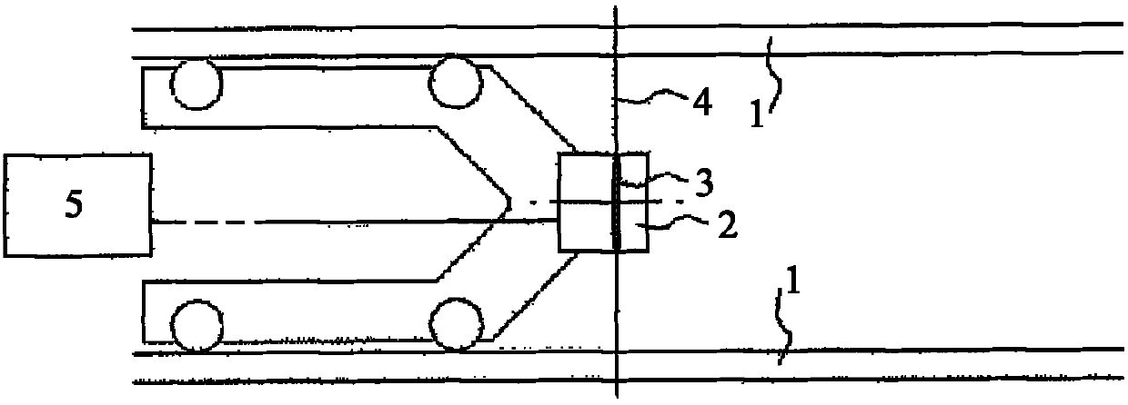
[0037] figure 1 A schematic embodiment of a system for detecting defects in a pipe wall 1 is shown, the system comprising an ultrasonic transmitter 2 arranged to emit ultrasonic signals from the inside of the pipe towards the pipe wall 1 via an emission opening , and receive the backscattered signal from the wall 1 of the tube via the entry opening. In this exemplary embodiment, the transmitter comprises an array of substantially circular ultrasonic transducers 3 arranged to emit and receive a plurality of ultrasonic waves having different main directions in a plane 4 substantially perpendicular to the axis of the pipe. Signal. The transmitters 3 are connected to a control module 5 arranged to energize the transmitters 3 to cause the transmitters to emit their signals (ie signal pulses). These signal pulses can be transmitted simultaneously or sequentially or mixed. The backscattered signal pulses can be received by the same transmitter in the time slots (reception slots) b...


PUM


Abstract

A system for detecting defects in a pipe wall (1), comprisesan ultrasonic transducer (2)which is arranged for emitting, via an exit opening, ultrasonic signals from the interior of thepipe towards its wall and for receiving, via an entrance opening, backscattered signals from the wall. The system is arranged to emit and receive a multitude of signals havingtheir main directions within a plane (4)mainly perpendicular to the pipe axis. The openings are configured to make the ultrasonic transmission signal diverge and / or to receive back signals from a diverging range of angles over a large areaof the pipe wall, by using openings with a diameter with magnitude of thewavelength of the ultrasonic signals. Sets of emitted and backscattered signalsfor different emission and reception positions areprocessed, in processing means (5), to form an image based on transmission times between emission and reception of backscattered signals.

Description

technical field [0001] The present invention relates to a method and a system for detecting defects in a pipe wall, comprising an ultrasound transducer (transducer,) arranged for emitting ultrasound from the inside of the pipe towards the pipe wall via an exit opening (exit opening) The signal and receives the backscattered signal from the tube wall via the entrance opening (entrance). Background technique [0002] Prior art ultrasonic systems (sometimes called (detection) "pigs") consist of an ultrasonic transducer and mirrors through which the sound is directed at the pipe wall. The same sensor receives backscattered echoes from the pipe wall. This existing technology has some limitations, such as: [0003] - The alignment of the sensors must be near perfect, otherwise, no echoes will be detected; [0004] - the surface of the pipe wall needs to be smooth, otherwise, the signal will be unusable; [0005] - Undetectable cracks and corrosion points. [0006] EP 1707956 ...

Claims


Application Information

Patent Timeline
Patent Type & Authority Applications(China)
IPC IPC(8): G01N29/04G01N33/34G01N3/32G01N29/06G01N29/07B06B1/06F16L55/26
CPCG01N29/04F16L2101/30G01N2291/2636G01N29/07G01N2291/044G01N2291/106G01N29/043G01N29/0654G01N29/0609Y10T70/454
Inventor 阿尔诺·威廉·福雷德里克·福尔克尔
Owner NEDERLANDSE ORG VOOR TOEGEPAST-NATUURWETENSCHAPPELIJK ONDERZOEK (TNO)
Learn More