Permanent magnet synchronous motor with wide field-weakening and speed regulation range

A permanent magnet synchronous motor and field-weakening speed regulation technology, which is applied to synchronous motors with stationary armatures and rotating magnets, synchronous machine parts, magnetic circuit rotating parts, etc., can solve the problems of permanent magnet demagnetization, etc. Achieve the effects of increasing the direct axis inductance, good application prospects, and solving the narrow range of field-weakening speed regulation

Active Publication Date: 2012-07-04
HARBIN INST OF TECH
View PDF0 Cites 0 Cited by
  • Summary
  • Abstract
  • Description
  • Claims
  • Application Information

AI Technical Summary

Problems solved by technology

[0016] The purpose of the present invention is to solve the problem that the demagnetization current of the existing permanent magnet synchronous motor will cause the demagnetization of the permanent magnet when the field is weakened in order to achieve the purpose of field weakening speed regulation, and to provide a permanent magnet synchronous motor with a wide field weakening speed regulation range. motor

Method used


Image

  • Permanent magnet synchronous motor with wide field-weakening and speed regulation range
  • Permanent magnet synchronous motor with wide field-weakening and speed regulation range
  • Permanent magnet synchronous motor with wide field-weakening and speed regulation range

Examples


specific Embodiment approach 1

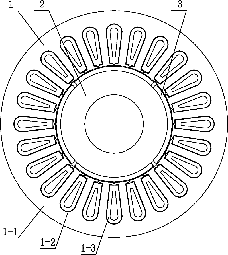
[0027] Specific implementation mode one: the following combination Figure 1 to Figure 5 Describe this embodiment, this embodiment includes a stator 1 and a rotor 2, an air gap is formed between the inner circular surface of the stator 1 and the outer circular surface of the rotor 2, and it is characterized in that: the stator 1 is composed of a stator core 1-1, a non- Composed of a magnetic isolation layer 1-2 and a magnetic sleeve 1-3,

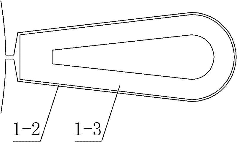
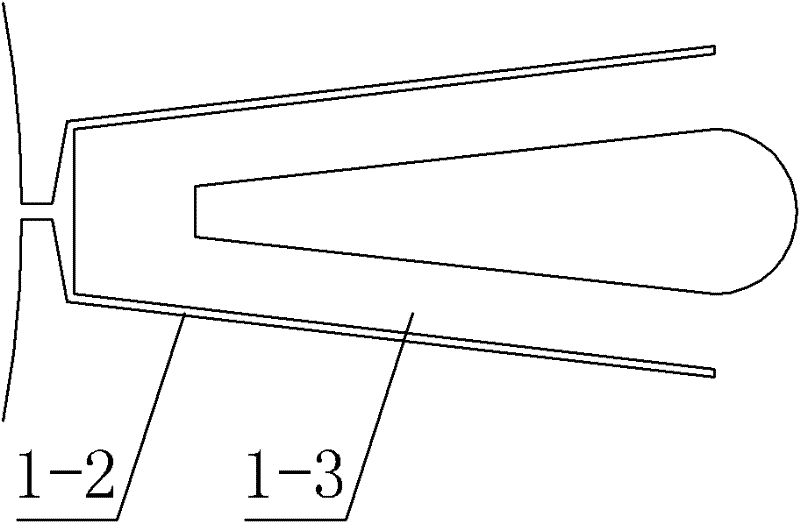
[0028] A plurality of stator slots are evenly distributed along the circumferential direction on the inner side wall of the stator core 1-1, and the stator slots axially penetrate the stator core 1-1, and a magnetic permeable sleeve 1-3 is arranged in each stator slot, and the magnetic permeable sleeve 1 The shape of -3 matches the shape of the stator slot, the thickness of the magnetic sleeve 1-3 is uniform, and a non-magnetic isolation layer 1-2 is provided between the stator slot and the magnetic sleeve 1-3;

[0029] The rotor 2 includes...

specific Embodiment approach 2

[0032] Specific implementation mode two: the following combination figure 1 Describe this embodiment. This embodiment is a further description of Embodiment 1. The permanent magnet 3 is a 2P block, P is the number of pole pairs of the motor, and the 2P permanent magnets 3 are evenly distributed along the circumferential direction and surface-attached on the On the cylindrical outer wall of the rotor 2. Other components and connections are the same as those in Embodiment 1.

[0033] In this embodiment, the rotor 2 adopts a surface-mounted permanent magnet 3 structure.

specific Embodiment approach 3

[0034] Specific implementation mode three: the following combination Figure 5 Describe this embodiment. This embodiment is a further description of Embodiment 1. The permanent magnets 3 are 2P blocks, P is the number of pole pairs of the motor, and the 2P permanent magnets 3 are evenly distributed in the rotor 2 along the circumferential direction. , and form a regular polygon in the circumferential direction of the rotor 2, the number of sides of the regular polygon is 2P, and the center line of the regular polygon coincides with the center line of the rotor 2, and the permanent magnet 3 axially penetrates the rotor 2, each A magnetic isolation hole 2-1 is provided on both sides of the permanent magnet 3 in the circumferential direction, and the magnetic isolation hole 2-1 is filled with a non-magnetic material. Other components and connections are the same as those in Embodiment 1.

[0035] The difference between this embodiment and the second embodiment is that the rotor ...


PUM


Abstract

The invention relates to a permanent magnet synchronous motor with a wide field-weakening and speed regulation range, which belongs to the technical field of motors and solves the problem that when the conventional permanent magnet synchronous motor performs field-weakening for fulfilling the aims of field weakening and speed regulation, a demagnetizing current can result in excitation loss of a permanent magnet. The motor comprises a stator and a rotor, wherein an air gap is formed between the internal circular surface of the stator and the external circular surface of the rotor; the stator consists of a stator iron core, non-magnetic conducting isolation layers and concentrating flux sleeves; a plurality of stator grooves are uniformly distributed on the inner side wall of the stator iron core along a circumferential direction; the stator grooves axially pass through the stator iron core; one concentrating flux sleeve is arranged in each stator groove; the shape of each concentrating flux sleeve is matched with that of each stator groove; the concentrating flux sleeves have uniform thickness; the non-magnetic conducting isolation layers are arranged between the stator grooves and the concentrating flux sleeves; the rotor comprises the permanent magnet; and the permanent magnet is arranged on the outer side wall of the rotor. The permanent magnet synchronous motor with the wide field-weakening and speed regulation range is used for realizing the field-weakening and speed regulation of the permanent magnet synchronous motor.

Description

technical field [0001] The invention relates to a permanent magnet synchronous motor with a wide and weak magnetic speed regulation range, belonging to the technical field of motors. Background technique [0002] Since the permanent magnet synchronous motor uses permanent magnet materials to provide excitation, its excitation is not easy to adjust. The permanent magnet synchronous motor has the characteristic that the back electromotive force is basically proportional to the speed. When the motor terminal voltage increases with the speed to the maximum voltage that the inverter can output, due to the limitation of the inverter capacity, the motor winding can no longer sink current , so it cannot maintain constant power operation at high speed. This defect of permanent magnet synchronous motor seriously limits its further application. Therefore, how to expand the constant power operating range of the permanent magnet synchronous motor has become an important subject of the ...

Claims


Application Information

Patent Timeline
Patent Type & Authority Patents(China)
IPC IPC(8): H02K21/14H02K21/02H02K1/27
Inventor 李立毅于吉坤曹继伟寇宝泉
Owner HARBIN INST OF TECH
Why Eureka
Try Eureka